Publicidad
Enlaces rápidos
DM6400.qxd
10/16/08
10:49 AM
Page 1
SPERRY
INSTRUMENTS
8 Function, 28 Range
Digital Multi-Meter
• Read this owners manual thoroughly before use and save.
SPERRY
INSTRUMENTS
The Professional's Choice®
Milwaukee, WI 53209
1-800-645-5398
www.sperryinstruments.com
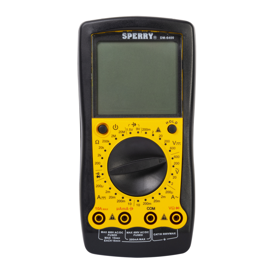
1. 3/12 digit LCD display
2. Test Lead icons on display indicate proper input terminals for easy attachment
of test leads
3. 28 position Function/Range dial
4. DC Volts/AC Volts
5 AC Amps
6 DC Amps
7. Resistance
8. Audible Continuity Test
9. Diode Test
10. Battery testing
11. Common input jack
12. Positive input jack
10
13. Durable drop resistant housing
1.0 METER FUNCTIONS
Meter type:
Functions:
Ranges:
Display Count:
7
Test Lead Icons:
Input impedance:
AC Volt Ranges:
DC Volt Ranges:
8
AC Amps:
9
DC Amps:
Resistance Ranges:
6
4
Battery Testing:
Over Range Indication: Displayed value > 1999, displays OL (The safety and
5
Polarity Indication:
Electro-Magnetic :
1 1 1 1
Agency Approvals:
Operating Temperature: 32°F - 104°F (0°C_40°C)
Relative Humidity:
32°F - 86°F below <75%, 86°F - 104°F<50%
Storage Temperature: 14°F - 122°F(-10°C - 50°C)
Dimension:
179mm x 88mm x 39mm
Weight:
Around 380g (including battery)
Altitude:
Maximum 2000m
Warranty info:
5 yr.
2.0 READ FIRST: IMPORTANT SAFETY INFORMATION
Read this operators manual thoroughly before using this mulitimeter. This manual is intended to provide basic information
regarding this meter and to describe common test procedures which can be made with this unit. Many types of appliance, machinery and other electrical
circuit measurements are not addressed in this manual and should be handled by experienced service technicians.
Use extreme caution when using this multimeter. Improper use of this meter can result in severe damage to personal injury or death. Follow all
instructions and suggestions in this operators manual as well as observing normal electrical safety precautions. Do not use this meter if you are unfamiliar
with electrical circuits and proper test procedures.
2.1 FOR YOUR SAFETY
1. Use extreme caution when checking electrical circuits.
2. Do not stand in wet or damp work areas when working with electricity.Wear rubber soled boots or shoes.
3. Do not apply more voltage or current than the set range of the multimeter will allow
4. Do not touch the metal probes of the test leads when making a measurement.
5. Replace worn test leads. Do not use test leads with broken or tattered insulation.
Replace damaged test leads with identical model number or electrical specifications before using the Meter.
6. Before you carrying out any measurement, make sure the display is normal after you turn on the meter.
7. Before using to check hazardous voltage, always test this Digital Multimeter on a known live circuit to verify that this Digital Multimeter is
working properly.
8. Use the Meter only as specified in this operating manual, otherwise the protection provided by the Meter may be impaired.
Equipment protected throughout by double insulation or reinforced insulation
Caution, Risk of Danger (See note)
9. Discharge a capacitor before measuring it.
10. Remove the test leads from the circuit being measured as soon as the test is completed. Never reset the function/range switch to
another range while the leads are still in contact with a circuit.
11. Do not measure voltage when the function/range switch is set on the resistance (ohms) settings. Do not measure current when the
meter is set on the resistance range. Never measure AC voltage when the meter is set on DC voltage. Setting the meter on the
incorrect function may burn out some of the internal circuitry and may pose a safety hazard.
SPERRY
INSTRUMENTS
8 funciones, 28 rangos
Multímetro digital
Lea completamente este manual del propietario antes del uso y consérvelo
•
para referencia futura.
1. Pantalla de cristal líquido de 0.65cm dígitos
2. Los iconos de conductores de prueba en pantalla indican los terminales de
entrada adecuados para facilitar la conexión de los conductores
3. Dial de 28 posiciones de función/rango
10
4. Voltios de CC/Voltios de CA
5. Amperios de CA
6. Amperios de CC
7. Resistencia
8. Prueba de continuidad audible
9. Prueba de diodo
10. Prueba de batería
7
11. Toma de entrada común
12. Toma de entrada positiva
13. Alojamiento durable, resistente a las caídas
8
9
Tipo de medidor:
Funciones:
4
6
Rangos:
Cuenta en pantalla:
Iconos de conductores de prueba: En pantalla indican los terminales de entrada
5
Impedancia de entrada:
Rangos de voltios de CA:
1 1 1 1
Rangos de voltios de CC:
Amperios de CA:
Amperios de CC:
200µA, 2mA, 20mA, 200mA y 10A, óptima precisión (0.8%+2)
Rangos de resistencia:
200ohm, 2kohm, 20kohm, 200kohm, 2M ohm y 20M ohm, óptima precisión (0.8%+3)
Prueba de batería:
(1.5V) 2000mV / (9V), óptima precisión (0.8%+5)
Indicación de sobre rango:
Valor mostrado > 1999, muestra OL (La seguridad y precisión solamente se garantizará dentro del rango de la
especificación) por la entrada.
Indicación de polaridad:
Aparece "-" para la polaridad negativa
Electro-Magnético :
Cuando está bajo frecuencia de 1V/m : precisión total = precisión asignada +5% del rango. Cuando está sobre
una frecuencia de 1V/m: no hay precisión asignada.
Aprobaciones de agencias:
ETL, CE (IEC/EN61010:, CAT III 600V, El grado de la contaminación 2
Temperatura operativa:
0°C - 40°C
Humedad relativa:
0°C - 30°C bajo <75%, 30°C - 40°C<50%
Temperatura de almacenamiento: -10°C - 50°C
Dimensiones:
179 mm x 88 mm x 39 mm
Peso:
Alrededor de 380 g (incluyendo la batería)
Altitud:
Máxima de 2000 m
Información de garantía:
5 años
2.0 LEER PRIMERO: INFORMACIÓN IMPORTANTE DE SEGURIDAD
Lea este manual del operador totalmente antes de usar este medidor. Este manual está destinado a brindar información básica referente a este
12. Damaged meters are not repairable nor is calibration possible. Damaged meters should be disposed of properly.
DM6400
2.2 OPERATING INSTRUCTIONS
1. Set the function/range switch to the proper position before making a measurement. When the voltage is not known, it MUST be determined that
the capacity of the selected range will handle the amount of voltage in the circuit (see #3 under "For Your Safety").
2. Avoid placing the meter in areas where vibration, dust or dirt are present. Do not store the meter in excessively hot, humid or damp places.
This meter is a sensitive measuring device and should be treated with the same regard as other electrical and electronic devices.
3. When the meter is not in use keep the meter turned off to keep the battery from discharging.
4. When disconnecting the test leads from the unit, always grasp the leads where the input jacks meet the tester housing. Do not pull the leads
out of the jacks by the insulated wire or transport the tester using the test leads as a carrying strap.
5. Do not immerse the meter in water or solvents. To clean the housing use a damp cloth with a minimal amount of mild soap.
NOTE: With any measurement made by this meter, there will be some fluctuation of the digital display. This is due to the meter's
sampling method. This unit samples at a rate of 2 times per second, thus the fluctuation of the readout.
3.0 FUNCTION BUTTONS
3.1POWER BUTTON TURNS METER POWER ON AND OFF
1. To conserve battery life the meter powers off automatically after 15 minutes of non use.
To disable auto off press the select button while turning the meter on.
3.2 HOLD BUTTON
©SPERRY INSTRUMENTS, INC.
1. Press HOLD once to enter data hold mode to freeze the displayed value.
2. Press HOLD again to exit data hold mode and resume normal measurement mode.
DIAL SETTINGS
4.0 DIAL SETTINGS
To avoid personal injury or damage to the Meter, do not attempt to measure voltages higher than 750V AC.
4.1 AC VOLTS V~
There are four ranges for measuring AC voltage, 2V, 20V, 200V, 750V. For more accurate measurements use the lowest setting possible without
exceeding the voltage setting. Ie. Use the 2V setting only if the voltage is 2 V or less.
1. Set the function/range switch to the appropriate AC V range.
2. Insert the black test lead into the COM input terminal.
3. Insert the red test lead into the V input terminal.
4. Touch the test leads to the circuit under test. With AC voltage, the polarity of the test leads is not a factor.
NOTE: It is best to touch one of the test leads to ground or Neutral first and then touch the 2nd test lead to the hot wire.
5. Read the value of the measurement displayed.
6. Typical AC Voltage measurements include wall outlets, appliance outlets, motors, light fixtures and switches.
4.2 DC VOLTS
To avoid personal injury or damage to the Meter, do not attempt to measure voltages higher than 1000V DC.
There are five ranges for measuring DC voltage, 200mV, 2V, 20V, 200V and 1000V. For more accurate measurements use the lowest range
possible without exceeding the voltage setting.
1. Set the function/range switch 10 Amps AC.
2. Insert the black (negative) test lead into the COM input terminal.
Manual
3. Insert the red (positive) test lead into the V input terminal.
8
4. Touch the test leads to the circuit under test. With DC voltage, the polarity of the test leads is a factor. Touch the black (common) test lead to
28
the negative DC source (ground) first and red (positive) test lead to the "live" source second.
1999
5. Read the value of the measurement displayed. If the leads are reversed a "-" indicator will appear on the display.
on display indicate proper input terminals for easy
6. Typical DC Voltage measurements include car batteries, automotive switches and household batteries.
attachment of test leads
10 Meg Ohm
4.3 AC AMPS A~
2V, 20V, 200V, 750V, best accuracy (0.8%+5)
200mV, 2V, 20V, 200V and 1000V, best accuracy
Never attempt an in-circuit current measurement where the open circuit voltage between terminals and ground is greater than 30V
(0.5%+5)
AC. If the fuse burns out during measurement, the meter may be damaged or personal injury may occur. Use proper terminals,
200µA, 2mA, 20mA, 200mA and 10A, best accuracy
function, and range for the measurement. When the test leads are connected to the Amp terminals, DO NOT connect them in
(1.0%+5)
200µA, 2mA, 20mA, 200mA and 10A, best accuracy
parallel across any circuit.
(0.8%+2)
200ohm, 2kohm, 20kohm, 200kohm, 2M ohm and 20M
To avoid possible damage to the Meter or to the equipment under test, check the Meter's fuses before measuring current. Use the
ohm, best accuracy (0.8%+3)
proper terminals, function, and range for the measurement. Never place the test leads in parallel with any circuit or component
(1.5V) 2000mV / (9V), best accuracy (0.8%+5)
when the leads are plugged into the current terminals.
accuracy will only be guaranteed within the specification
Do not attempt to measure current exceeding 10Amps AC. If you are not sure if the current exceeds 10Amps do not attempt to
range) by the input.
measure current with this meter.
"-" is displayed for negative polarity
1. Set the rotary switch to 10 Amps AC.
When it is under 1V/m frequency : total accuracy =
2. Insert the black test lead into the COM input terminal.
assigned accuracy +5% of the range. When it is over
3. Insert the red test lead into the 10A max terminal.
1V/m frequency: there is no assigned accuracy.
4. Turn off power to the circuit to be measured.
ETL, CE (IEC/EN61010:, CAT III 600V, Pollution Degree 2
5. Open the circuit to be measured.
6. Touch the red test lead to one side of the break in circuit and the black test lead to the other side of the break in circuit. For AC Amp
measurement the polarity of the leads does not matter.
7. Return power to the circuit.
8. Read the amps on the display.
Notes: When measuring AC Amps this meter displays the effective value of the sine wave (mean value response).
When the measured current is <5 amps continuous measurement is acceptable.
When the measured current is 5-10 amps do not exceed 10 seconds of continuous measurement. Wait 15 minutes before
performing additional current measurements.
Always start with the highest 10A~ measurement range and reduce the range in steps once you know that the current does not exceed the next
lower range. The red test lead will be inserted into the µA mA input terminal for measuring amps 200m Amps. Always turn of power to circuit
and remove the leads from the circuit before removing and reinserting the leads into the meter's input terminals. Once the measurement is
complete, immediately remove the test leads from the circuit under test and remove the test leads from the input terminals of the meter.
4.4 DC Amps A
Never attempt an in-circuit current measurement where the open circuit voltage between terminals and ground is greater than 60V
DC. If the fuse burns out during measurement, the Meter may be damaged or personal injury may occur. Use proper terminals,
function, and range for the measurement. When the test leads are connected to the Amp terminals, DO NOT connect them in
parallel across any circuit.
To avoid possible damage to the Meter or to the equipment under test, check the meter's fuses before measuring current. Use the
proper terminals, function, and range for the measurement. Never place the test leads in parallel with any circuit or component
when the leads are plugged into the current terminals.
Do not attempt to measure current exceeding 10Amps DC. If you are not sure if the current exceeds 10Amps do not attempt to
measure current with this meter.
1. Set the rotary switch to 10 A (DC). Insert the black test lead into the COM input terminal.
2. Insert the red test lead into the 10A max terminal.
3. Turn off power to the circuit to be measured.
4. Open the circuit to be measured.
5. Touch the red test lead to the positive side of the break in circuit and the black test lead to the negative side of the break in circuit for DC Amp
measurement.
6. Return power to the circuit.
7. Read the amps on the display.
When the measured current is <5 amps continuous measurement is acceptable.
When the measured current is 5-10 amps do not exceed 10 seconds of continuous measurement. Wait 15 minutes before
performing additional current measurements.
Always start with the highest 10A measurement range and reduce the range in steps once you know that the current does not exceed the next
lower range. The red test lead will be inserted into the µA mA input terminal for measuring amps ≤ 200m Amps. Always turn of power to circuit
and remove the leads from the circuit before removing and reinserting the leads into the meter's input terminals. Once the measurement is
complete, immediately remove the test leads from the circuit under test and remove the test leads from the input terminals of the meter.
4.5 RESISTANCE
Ω
There are six ranges for measuring resistance 200, 2K, 20K, 200K, 2 M, and 20Meg Ohms. For more accurate measurements use the lowest
medidor y a describir procedimientos comunes de prueba que pueden realizarse con esta unidad. Muchos tipos de mediciones de circuitos
DM6400
eléctricos, artefactos y maquinarias no se describen en este manual y deben realizarlas los técnicos de servicio experimentados.
Tenga sumo cuidado al utilizar este multímetro. El uso indebido de este medidor puede producir graves daños
materiales, además de lesiones físicas serias o fatales. Siga todas las instrucciones y sugerencias en este manual del operador y observe
también las precauciones de seguridad normales con la electricidad. No use este medidor si no está familiarizado con los circuitos eléctricos y
los procedimientos correctos de prueba.
2.1 PARA SU SEGURIDAD
1. Tenga sumo cuidado al revisar circuitos eléctricos.
2. No se pare sobre áreas de trabajo mojadas o húmedas al trabajar con electricidad. Use botas o zapatos con suelas de goma.
3. No aplique más voltaje o corriente que lo permitido por el rango establecido del multímetro
4. No toque las sondas de metal de los electrodos o conductores de prueba al hacer una medición.
5. Reemplace los conductores de prueba desgastados. No use conductores de prueba con aislamiento roto o deshilachado.
Reemplace los conductores de prueba dañados por el número de modelo idéntico o conforme a las especificaciones eléctricas antes de usar el
medidor.
6. Antes de tomar ninguna medición, revise que la pantalla esté normal después de encender el medidor.
7. Antes de usarlo para revisar el voltaje peligroso, siempre pruebe este multímetro digital en un circuito que se sepa
energizado para confirmar que el medidor funciona debidamente.
8. Use el medidor solamente como se especifica en este manual operativo, de lo contrario la protección provista por el medidor
puede verse perjudicada.
El equipo está protegido totalmente mediante doble aislamiento o aislamiento reforzado
Precaución, riesgo de peligro (Vea la nota)
9. Descargue un capacitor antes de medirlo.
Manual
10. Retire los conductores de prueba del circuito que mida tan pronto termine la prueba. Nunca restablezca el interruptor de función/rango en
8
otro rango mientras estén los conductores todavía en contacto con un circuito.
28
11. No mida el voltaje cuando el interruptor de función/rango esté en las selecciones de resistencia (ohmios). No mida la corriente cuando el
1999
medidor esté en el rango de resistencia. Nunca mida el voltaje de CA cuando el medidor esté en voltaje de CC. Si se establece el medidor en
la función incorrecta puede quemar algunos de los circuitos internos y puede presentar un peligro de seguridad.
adecuados para facilitar la conexión de los
12. Los medidores dañados no son reparables ni es posible calibrarlos. Los medidores dañados deben descartarse.
conductores
10 Meg Ohmios
2.2 INSTRUCCIONES DE OPERACIÓN
2V, 20V, 200V, 750V, óptima precisión (0.8%+5)
1. Ponga el interruptor de función/rango en la posición adecuada antes de comenzar a medir. Cuando no se conozca el voltaje, DEBE
200mV, 2V, 20V, 200V y 1000V, óptima
determinarse que la capacidad del rango seleccionada aceptará la cantidad de voltaje del circuito (vea el número 3 de la sección "Para su
precisión (0.5%+5)
seguridad").
200µA, 2mA, 20mA, 200mA y 10A, óptima
2. Evite poner el medidor en áreas donde haya vibración, polvo o suciedad. No almacene el medidor en lugares excesivamente calientes o
precisión (1.0%+5)
húmedos.
Este medidor es un dispositivo sensible para medir y debe tratarse con la misma consideración que otros aparatos eléctricos y electrónicos.
3. Cuando no esté en uso el medidor manténgalo apagado para que no se descargue la batería.
4. Al desconectar los conductores de prueba de la unidad, siempre tome los conductores donde se encuentran las tomas de entrada con el
alojamiento del probador. No saque los conductores de las tomas tirando del cable aislado ni transporte el probador usando los conductores
de prueba como correa para llevar.
5. No sumerja el medidor en agua ni solventes. Para limpiar el alojamiento use un paño húmedo con una mínima cantidad de
jabón suave.
NOTA: Con cualquier medida efectuada por este medidor, habrá algo de fluctuación de la pantalla digital. Esto se debe al método de
muestreo del medidor . Esta unidad muestrea a razón de 2 veces por segundo, por eso se produce la fluctuación de la lectura.
range possible without exceeding the setting value. When measuring resistance always make sure the power to the circuit is off.
1. Set the function/range switch to the appropriate resistance setting to measure Ω (ohms).
2. Insert the black (negative) test lead into the COM input terminal.
3. Insert the red (positive) test lead into the VΩ input terminal.
4. Touch the test leads to the resistor or non-energized component to be measured. Use the 20 M Ohm range when testing for resistance values
in electronic components such as resistors and potentiometers. If the value of the component falls within the range of a lower setting, reset the
function/range switch to that setting for a more accurate reading.
5. Read the value of the measurement displayed. With resistance measurements, the polarity of the test leads is not a factor.
6. Typical resistance/continuity measurements include resistors, potentiometers, switches, extension cords and fuses.
4.6 CONTINUITY
To avoid damages to the Meter or to the devices under test, disconnect circuit power and discharge all the high-voltage capacitors
before measuring resistance.
Do not input 60V DC or 30V AC to avoid personal harm. Do not use on energized circuits.
1. Insert the red test lead into VΩ terminal and the black test lead into the COM terminal.
2. Set the function switch to
3. Connect the test leads across with the object being measured.
4. The buzzer sounds continuously if the resistance of a circuit under test is°‹10Ω, it indicates the circuit is in good connection.
5. The buzzer does not sound if the resistance of a circuit under test is°100Ω, it indicates a possible broken circuit.
6. Read the resistance value on the display.
Note
• Open circuit voltage is around 3V.
4.7 DIODE TESTING
Use the diode test to check diodes, transistors, and other semiconductor devices. The diode test sends a current through the semiconductor
junction, and then measures the voltage drop across the junction. A good silicon junction drops between 0.5V and 0.8V.
To test out a diode while removed from a circuit, connect the Meter as below:
1. Insert the black (negative) test lead into the COM input terminal.
2. Insert the red (positive) test lead into the VΩ input terminal.
3. Set the function switch to diode position "
"
4. For forward voltage drop readings on any semiconductor component, place the red test lead on the component's anode and place the black
test lead on the component's cathode.
5. Read the nearest value of the diode's forward voltage drop as displayed.
Notes
• In a circuit, a good diode should still produce a forward voltage drop reading of 0.5V to 0.8V; however; the reverse voltage drop
reading can vary depending on the resistance of other pathways between the probe tips.
• Connect the test leads to the proper terminals as in figure above to avoid error display. The LCD displays OL indicating open-circuit
for improper connection.
• Open circuit voltage is approximately 3V.
5.0 HOUSEHOLD BATTERY TESTING
There are two ranges for measuring common household batteries, 1.5 V and 9 V.
1. Insert the black (negative) test lead into the COM input terminal.
2. Insert the red (positive) test lead into the
terminal.
3. Set the function/range switch to the appropriate battery position.
4. Touch the test leads to the positive and negative terminals on the battery. With DC voltage, the polarity of the test leads is a factor. Touch the
black (common) test lead to the negative (-) terminal and the red test lead to the positive (+) terminal.
5. Read the value of the measurement displayed. If the leads are reversed a "-" indicator will appear on the display.
6.0 BATTERY REPLACEMENT
To avoid false readings, which could lead to possible electric shock or personal injury, replace the battery as soon as the battery
indicator appears
1. Disconnect the connection between the test leads and the circuit under test, and remove the test leads from the input terminals of the meter.
2. Turn the Meter power off.
3. Remove the screw from battery door, and separate the battery door from the case bottom.
4. Remove the battery from the contacts, noting the polarity of the battery terminals and contacts.
5. Replace with one fresh 9 volt battery (NEDA 1604 6F22 006P)
Note: Do not use rechargeable batteries in this unit.
6. Carefully replace the battery cover and tighten the screw. Do not overtighten the screw as this may strip the threads in the meter housing.
7.0 FUSE REPLACEMENT
To avoid personal injury or damage to the Meter, use specified fuses ONLY in accordance with the following procedure.
To replace the Meter's fuse:
1. Turn the Meter off and remove test leads from the input terminals.
2. Remove the rubber boot from the Meter.
3. Remove the 3 screws from the case bottom, and separate the case top from the case bottom.
4. Remove the fuse by gently prying one end loose, then remove the fuse from its bracket.
5. ONLY install replacement fuses of the identical type and specification as follows and make sure that all fuses are inserted firmly into the fuse
holder brackets.
Fuse 1: 10A, H240V, fast type, 6x25 mm.
Fuse 2: 1A,H 250V, fast type, 6x25 mm.
6. Rejoin the case bottom and case top, and reinstall the 3 screws. Be careful not to overtighten the screws. Reinstall the rubber boot.
Replacement of the fuses is seldom required. A burned fuse suggests improper operating procedures.
A. GENERAL SERVICE
• Periodically wipe the case with a damp cloth and mild detergent. Do not use abrasives or solvents.
• To clean the terminals use a cotton swab and detergent, as dirt and moisture in the terminals can affect readings.
• Turn the Meter power off when it is not in use.
• Take out the battery when it is not used for a long time.
• Do not use or store the Meter in a place of humidity, high temperature.
3.0 Botones de funciones
3.1 Botón de encendido enciende y apaga el medidor
1. Para conservar la vida de batería los poderes de metro de automáticamente después de 15 minutos del no-uso. Para incapacitar el auto
aprieta lejos el botón selecto mientras prendiendo el metro.
3.2 Botón HOLD
1. Presione una vez el botón de espera (HOLD) para ingresar al modo de espera de datos para congelar el valor mostrado.
2. Presione de nuevo el botón de espera (HOLD) para salir de este modo y reanudar el modo normal de medición.
SELECCIONES DEL DIAL
4.0 SELECCIONES DEL DIAL
Para evitar lesiones físicas o daños al medidor, no intente medir voltajes que superen 750V CA.
4.1 VOLTIOS DE CA
Hay cuatro rangos para medir voltaje de CA, 2V, 20V, 200V, 750V. Para mediciones más precisas use al selección más baja posible sin exceder
la selección de voltaje. Ie. Use la selección de 2V solamente si el voltaje es ≤ 2V.
1. Ponga el interruptor de función/rango en la posición adecuada (CA_V).
2. Inserte el conductor de prueba negro en el terminal de entrada COM.
3. Inserte el conductor de prueba rojo en el terminal de entrada V.
4. Toque el circuito a prueba con los conductores de prueba. Con voltaje de CA, la polaridad de los conductores de prueba no es un factor.
NOTA: Es mejor tocar tierra o neutro primero con uno de los conductores de prueba y luego tocar el cable energizado con el 2do
conductor de prueba.
5. Lea el valor de la medida mostrada.
6. Las medidas típicas de voltaje de CA incluyen receptáculos de pared, enchufes para electrodomésticos, motores, luces e interruptores.
4.2 VOLTIOS DE CC
Para evitar lesiones físicas o daños al medidor, no intente medir voltajes que superen 1000V CC.
Hay cinco rangos para medir voltaje CC, 200mV, 2V, 20V, 200V y 1000V. Para mediciones más precisas use el rango más bajo posible sin
exceder la selección de voltaje.
1. Ponga el interruptor de función/rango en el rango adecuado de V CC.
2. Inserte el conductor de prueba negro (negativo) en el terminal de entrada COM.
3. Inserte el conductor de prueba rojo (positivo) en el terminal de entrada V.
4. Toque el circuito a prueba con los conductores de prueba. Con voltaje de CC, la polaridad de los conductores de prueba es un factor. Toque
con el conductor de prueba negro (común) la fuente CC negativa (tierra) en primer lugar, y con el conductor de prueba rojo (positivo) la fuente
"energizada" en segundo lugar.
5. Lea el valor de la medida mostrada. Si los conductores están invertidos aparecerá un indicador "-" en la pantalla.
6. Las medidas típicas de voltaje de CC incluyen baterías de automóviles, interruptores automotrices y baterías caseras.
4.3 AMPERIOS DE CA A~
Nunca intente hacer una medición de corriente dentro de circuitos donde el voltaje de circuito abierto entre terminales y tierra
sea mayor que 30V CA. Si se quema el fusible durante la medición, puede dañarse el medidor o causar lesiones físicas. Use
los terminales, la función y el rango que sean adecuados para la medición. Cuando los conductores de prueba estén
conectados a los terminales de Amp., NO los conecte en paralelo en ningún circuito.
Para evitar posible daño al medidor o al equipo a prueba, revise los fusibles del medidor antes de medir la corriente. Use los
terminales, la función y el rango que sean adecuados para la medición. Nunca ponga los conductores de prueba en paralelo
con ningún circuito o componente cuando los conductores estén enchufados en los terminales de corriente.
No intente medir la corriente que exceda 10Amps CA. Si no está seguro de que la corriente exceda 10Amps no intente medir
la corriente con este medidor.
1. Fije el interruptor rotatorio en A~.
2. Inserte el conductor de prueba negro en el terminal de entrada COM.
3. Inserte el conductor de prueba rojo en el terminal de 10A máx.
4. Apague la alimentación al circuito que va a medir.
5. Abra el circuito que va a medir.
6. Toque un lado del circuito de interrupción con el conductor de prueba rojo y otro lado del circuito de interrupción con el conductor de prueba
negro. No importa la polaridad de los conductores para las mediciones de Amp de CA.
7. Vuelva a encender el circuito.
8. Lea los amperios en la pantalla.
Notas: Al medir los Amps de CA este medidor muestra el valor efectivo de la onda sinusoidal (respuesta de valor medio).
Cuando la corriente medida es <5 amps es aceptable la medición continua.
Cuando la corriente medida es de 5-10 amps no exceda 10 segundos de medición continua. Espere 15 minutos antes de
realizar mediciones adicionales de corriente.
Siempre empiece con el rango más alto de medición de 10A~ y reduzca el rango en pasos una vez que sepa que la corriente no supera el
rango más bajo. Se insertará el conductor rojo en el terminal de entrada µA mA para medir amperios 200m Amps. Siempre apague la
Publicidad

Manuales relacionados para Sperry instruments DM6400


Resumen de contenidos para Sperry instruments DM6400
- Página 1 6. Read the resistance value on the display. The Professional’s Choice® ©SPERRY INSTRUMENTS, INC. 1. Press HOLD once to enter data hold mode to freeze the displayed value. 2. Press HOLD again to exit data hold mode and resume normal measurement mode.
- Página 2 DM6400.qxd 10/16/08 10:49 AM Page 2 alimentación al circuito y retire los conductores del circuito antes de quitar y reinsertar los conductores en los terminales de entrada del medidor. 2. Apague la alimentación del medidor. Una vez terminada la medición, desconecte inmediatamente los conductores de prueba del circuito que está probando, además retire los 3.