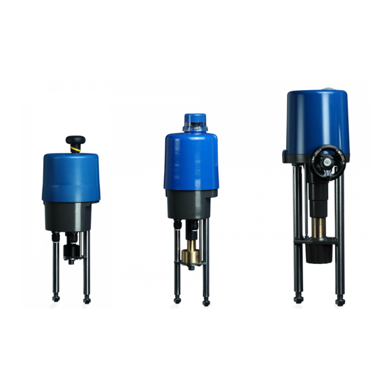
Resumen de contenidos para PS Automation PSL Serie
- Página 1 Kurz-Betriebsanleitung PSL Short Operating Instructions PSL Manual de operación resumido PSL Version 2018/06/27 Art.No.: 8034359 © 2017 PS Automation GmbH...
-
Página 3: Tabla De Contenido
Inhaltsverzeichnis 1. Betriebsbedingungen 2. Handbetätigung 3. Armaturenanbau 4. Elektroanschluss 5. Einstellung der Endschalter 6. Inbetriebnahme 7. Zubehör Table of content 1. Operating conditions 2. Manual operation 3. Valve mounting 4. Electric supply 5. Setting of the limit switches 6. Commissioning 7. -
Página 4: Betriebsbedingungen
Es ist sicherzustellen, dass jede Person, die mit der Aufstellung, Inbetriebnahme, Bedienung, Wartung und Reparatur der Antriebe beauftragt ist, die ausführliche Betriebsanleitung und besonders das Kapitel „Sicherheit“ gelesen und verstanden hat. Vorsicht! Lebensgefährliche elektrische Spannung kann anliegen! Sach- oder Personenschäden sind durch geeignete Maßnahmen und Einhaltung der Sicherheitsstandards zu vermeiden! 1. -
Página 5: Einstellung Der Endschalter
Die Gebäudeinstallation sowie die Überstromschutzeinrichtung und Überspannungsschutzeinrichtungen müssen entsprechend der Norm DIN IEC 60364-4-41, Schutzklasse I bzw. Schutzklasse III bei 24VAC/24VDC sowie DIN IEC 60364-4-44 entsprechend der verwendeten Überspannungskategorie des Antriebs ausgeführt sein. Alle Netzanschluss- und Steuerleitungen müssen mechanisch durch geeignete Maßnahmen vor den Anschlussklemmen gegen unabsichtliches Lösen gesichert werden. -
Página 6: Inbetriebnahme
Schaltnocke Spindelmutter einfahrend Schaltnocke Spindelmutter ausfahrend 6. Inbetriebnahme Haube schließen und Antrieb per Handrad in die Mitte des Ventilhubes fahren. Netzspannung einschalten. Stellsignal für AUF- und ZU- Richtung kurz einschalten und prüfen, ob der Antrieb in die vorgegebene Richtung positioniert. -
Página 7: Operating Conditions
Please ensure that the detailed operating instructions and the chapter on "Safety" in particular have been read and understood by all personnel involved in the installation, start- up, operation, maintenance and repair of the actuators. Caution! Dangerous electrical voltage can be present! Avoid personal or material damages by observing applicable regulations and safety standards! 1. -
Página 8: Setting Of The Limit Switches
Electric installation as well as over-current and overvoltage protection devices must be conform to the standard DIN IEC 60364-4-41, protective class I resp. protection class 3 (24VAC/24VDC) and also to the standard DIN IEC 60364-4- 44 according to the applied overvoltage category of the actuator. Please protect all of the power supply and control cables in front of the terminals mechanically by using suitable measures against unintentional loosening. -
Página 9: Commissioning
Switching cam retracting spindle nut Switching cam extending spindle nut 6. Commissioning Close the cover and drive the actuator to the center of the stroke using the handwheel. Switch on the mains. Switch the setting signal briefly between OPEN and CLOSE and check that the actuator operates in the correct direction. -
Página 10: Condiciones De Operación
Asegurese que todo el personal de puesta en marcha, mantenimiento y de la planta haya leido detalladamente el manual de operación y mantenimiento. Especialmente el capitulo de „Seguridad“. Atención! Puede haber presencia de tensión electrica! Se debe respetar la normativa vigente de seguridad y de prevención de riesgos laborales! 1. -
Página 11: Ajuste De Los Finales De Carrera
Todos los cables de alimentación y de mando deben protegerse mecánicamente mediante unas medidas adecuadas para evitar que se suelten involuntariamente. Nunca instale los cables de alimentación y mando juntos en una misma linea. Siempre deben ir en 2 lineas separadas. -
Página 12: Puesta En Marcha
= PSAP con módulo de relé externo requerido = sólo se debe utilizar con contactor reversible de arranque )³ = se debe utilizar con tension 24 V o 115-230 V PS Automation GmbH Gesellschaft für Antriebstechnik Philipp-Krämer-Ring 13 D-67098 Bad Dürkheim Tel.: +49 (0) 63 22 - 94980 –...


