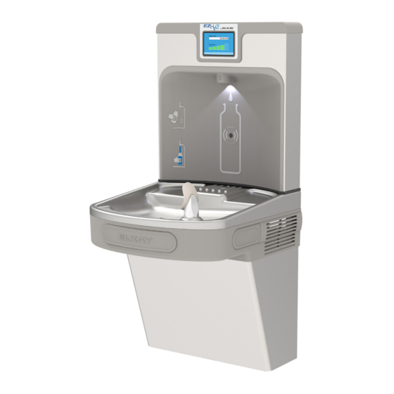
Elkay EZ Serie Manual De Instalación, Cuidado Y Utilización
Ocultar thumbs
Ver también para EZ Serie:
- Manual de instalación, cuidado y utilización (21 páginas) ,
- Manual de instalación, cuidado y uso (10 páginas) ,
- Manual de instalacion y uso (10 páginas)
Publicidad
Enlaces rápidos
EZF(S)8*1G, 2G, 3G
LZF(S)8*1G, 2G, 3G
INSTALLATION, CARE & USE MANUAL
Manual de Instalación, Cuidado y Utilizaci
Manuel d'installation/entretien/utilisation
EZ™ & LZ™ Series Barrier-Free Water Coolers
EZ™ & LZ™ La Barrera de la serie Liberta Agua Coolers
EZ™ & LZ™ Coolers d'Eau de Barrière-Libère de feuilleton
Model EZS8L
WWW.RESTROOMDIRECT.COM
704 • 937• 2673
129 Oak Park Dr., Unit A, Mooresville, NC 28115
COMMERCIAL RESTROOM ACCESSORIES
Page 1
1000003086 (Rev. A - 02/16)
Publicidad

Resumen de contenidos para Elkay EZ Serie
- Página 1 EZF(S)8*1G, 2G, 3G LZF(S)8*1G, 2G, 3G INSTALLATION, CARE & USE MANUAL Manual de Instalación, Cuidado y Utilizaci Manuel d’installation/entretien/utilisation EZ™ & LZ™ Series Barrier-Free Water Coolers EZ™ & LZ™ La Barrera de la serie Liberta Agua Coolers EZ™ & LZ™ Coolers d’Eau de Barrière-Libère de feuilleton Model EZS8L WWW.RESTROOMDIRECT.COM 704 •...
- Página 2 EZF(S)8*1G, 2G, 3G LZF(S)8*1G, 2G, 3G Note: Danger! Electrical shock hazard. Disconnect power before servicing unit. Nota: peligro! Peligro de descarga eléctrica. Desconecte antes de reparar la unidad l’appareil. Remarque : Danger ! Risque de choc électrique. Débrancher avant de réparer Uses HFC-134A refrigerant Usa refrigerante HFC-134A Utilise du fluide frigorigéne HFC-134A...
- Página 3 EZF(S)8*1G, 2G, 3G LZF(S)8*1G, 2G, 3G WWW.RESTROOMDIRECT.COM 704 • 937• 2673 129 Oak Park Dr., Unit A, Mooresville, NC 28115 COMMERCIAL RESTROOM ACCESSORIES Fig. 2 Page 3 1000003086 (Rev. A - 02/16)
-
Página 4: Limpieza
EZF(S)8*1G, 2G, 3G LZF(S)8*1G, 2G, 3G HANGER BRACKETS & TRAP INSTALACIÓN DE LOS SOPORTES INSTALLATION DES SUPPORTS FIJADORES Y EL PURGADOR DE SUSPENSION ET DU SIPHON INSTALLATION Retire el soporte fijador que se encuentra conectado a 1) Retirez le support de suspension fixé au dos du 1) Remove hanger bracket fastened to back of cooler by la parte posterior del enfriador sacando un (1) tornillo. -
Página 5: Atienda A Instrucciones
EZF(S)8*1G, 2G, 3G LZF(S)8*1G, 2G, 3G Service Instructions Lower and Upper Shroud To access the refrigeration system and plumbing connections, remove four screws from bottom of cooler to remove the lower shroud. To remove the upper shroud for access to the pushbars, 12 - Bubbler regulator, solenoid valve or other components located in the top of the unit, remove lower shroud, Assembly... -
Página 6: Cleaning The Strainer
EZF(S)8*1G, 2G, 3G LZF(S)8*1G, 2G, 3G NOTE: When installing replacement bubbler and pedes- tal, tighten nut only to hold parts snug in position. Do Not Overtighten. NOTA: Al instalar el grifo y pedestal de reemplazo, apriete la tuerca unicamente para mantener las piezas en una posicion adjustada. -
Página 7: Descripción
EZF(S)8*1G, 2G, 3G LZF(S)8*1G, 2G, 3G OVERLOAD COLD CONTROL Fig. 8 115V Wiring Diagram Esquema eléctrico 115V SOLENOID Diagramme de câblage 115V VALVE RELAY OVERLOAD COLD CONTROL SHORT WHITE LEAD FROM POWER CORD SOLENOID Fig. 9 VALVE TO "N" TERMINAL ON 220V Wiring Diagram POWER INLET Esquema eléctrico 220V... - Página 8 POUR OBTENIR DES PIÈCES, CONTACTEZ VOTRE DISTRIBUTEUR LOCAL OU COMPOSEZ LE 1.800.834.4816 PRINTED IN U.S.A. IMPRESO EN LOS E.E.U.U. IMPRIMÉ AUX É.-U. ELKAY MANUFACTURING COMPANY • 2222 CAMDEN COURT • OAK BROOK, IL 60523 • 630.574.8484 1000003086 (Rev. A - 02/16) Page 8...


