Tabla de contenido
Publicidad
Idiomas disponibles
Idiomas disponibles
Enlaces rápidos
Publicidad
Capítulos
Tabla de contenido

Resumen de contenidos para Kawasaki KRH300A
-
Página 2: Read This First
Careless or improper use can cause serious injury. Obey the safety instructions contained in this manual as well as all applicable governmental and workplace safety standards, regulations and ordinances. Your authorized Kawasaki dealer can show you how to operate your hand held blower properly. - Página 3 Hand Held Blower Modifying the hand held blower may make it unsafe. Never modify your hand held blower, except as advised by Kawasaki in writing. Use only Kawasaki supplied or approved attachments and repair parts. Recoil starter rope can injure you if released suddenly.
-
Página 4: Environmental Protection
ENVIRONMENTAL PROTECTION To protect our environment, properly dispose of used batteries, engine oil, gasoline, coolant, or other components that you might discard. Consult your authorized Kawasaki dealer or local environmental waste agency for the proper disposal procedures. -
Página 5: Emission Control Information
A minimum of 87 octane of the antiknock index is recommended. The antiknock index is posted on service station pumps in the U.S.A. Emission Control Information To protect the environment in which we all live, Kawasaki has incorporated exhaust emission control system (EM) in compliance with applicable regulations of the United States Environmental Protection Agency and the California Air Resources Board. - Página 6 The Kawasaki Limited Emission Control System Warranty requires that you return your hand held blower to an authorized Kawasaki dealer for remedy under warranty. Please read the warranty carefully, and keep it valid by complying with the owner’s obligations it contains. Tampering with Emission Control System Prohibited...
- Página 7 Kawasaki Motors Corp., U.S.A. Although every possible care has been taken to make this manual as complete and accurate as possible, Kawasaki cannot guarantee against errors and omissions. Due to improvements in design and performance during production, procedures and specifications are subject to change without prior notice.
-
Página 8: Tabla De Contenido
TABLE OF CONTENTS Specifications................8 Assembly and Preparation ............9 ............ 9 Location of Parts and Tools Location of Parts for Engine Assembly .........10 Location of Labels ..............10 Blower Pipes Installation ............12 Fuel and Oil................13 Operating Instructions .............. 15 Starting the Engine............... 15 Warming Up ................ -
Página 9: Specifications
8 SPECIFICATIONS Specifications Model KRH300A/AC Max. Air olume /min (CFM) 12.5 (450) Max. Air speed m/s (MPH) 56 (125) 340 x 245 x 360 Length x Width x Height Metric (in.) (13.4 x 9.7 x 14.2) 4.4 (9.7) eight kg (lbs) -
Página 10: Assembly And Preparation
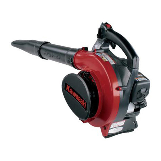
ASSEMBLY AND PREPARATION 9 Assembly and Preparation Location of Parts and Tools A. Engine assembly B. Handle C. Blower housing D. Throttle lever E. Straight pipe F. End pipe G. Cover H. Goggle I. Spark plug wrench... -
Página 11: Location Of Parts For Engine Assembly
10 ASSEMBLY AND PREPARATION Location of Parts for Engine Assembly Location of Labels A. Engine cover A. Emission certification label B. Air cleaner assembly/Carburetor B. Warning label C. Recoil starter D. Recoil starter grip E. Priming pump F. Fuel tank G. - Página 12 ASSEMBLY AND PREPARATION 11 Labels W A R N I N G D A N G E R ROTATING FAN! WHEN USED AS A BLOWER THE AIR INTAKE SCREEN MUST BE CLOSED AND SECURE WITH THE KNOB NUT, WHEN USED AS A VACUUM THE VACUUM TUBE AND BAG MUST BE IN PLACE AND SECURELY FASTENED.
-
Página 13: Blower Pipes Installation
12 OPERATING INSTRUCTIONS Blower Pipes Installation WARNING Stop the engine before installing or removing blower pipes. Align groove in straight pipe B with pegs D on blower housing A and slide straight pipe B on to housing (1). Rotate pipe B clockwise to lock it into place (2). Align groove in end pipe C with pegs D on pipe B and slide pipe C until proper position (3). -
Página 14: Fuel And Oil
ASSEMBLY AND PREPARATION Minimum Fuel and Oil Octane Rating Method Rating (RON + MON) Type: Antinock Index The fuel is mixture of gasoline and oil. A 50 to 1 mixture Researc h Octane Number (RON) is recommended (50 parts gasoline to 1 part oil). Mix it thoroughly before pouring it into the hand held blower Recommended engine oil: High quality 2-stroke air... - Página 15 ASSEMBLY AND PREPARATION NOTE Recommended Mixing Ratio (50:1) Do not use the gasoline that has been stored longer Gasoline 2 stroke oil than two months. Liter To ensure proper starting at low ambient temperatures, 3.79 use fresh, winter grade fuel. Filling the Tank: 11.4 Level the engine before fueling.
-
Página 16: Operating Instructions
OPERATING INSTRUCTIONS 15 Operating Instructions CAUTION Starting the Engine Engine speed can not be adjusted if the throttle Checking throttle operation lever and setting lever does not move Move the throttle lever and setting lever through its full smoothly all the way and without binding. range of motion. - Página 17 16 OPERATING INSTRUCTIONS Slowly push the priming pump several times until the fuel comes out of the overflow tube. When the gasoline flows, stop pushing the priming pump. NOTE The fuel that flows by pushing the priming pump is Running position Starting position designed to return to the fuel tank.
- Página 18 OPERATING INSTRUCTIONS 17 Idle Position Half Position WARNING Full Throttle Position The recoil starter rope can cause injury if it is released suddenly. When starting the engine, grasp the recoil starter firmly by the grip. Do not grasp the starter rope itself. Always control the rope during rewind into the housing.
-
Página 19: Warming Up
18 OPERATING INSTRUCTIONS NOTE Warming Up Should the engine fail to start, do not try to pull the recoil starter grip too many times with the enrichment After starting the engine, run the engine at the idling lever at the "Starting" position. This will cause the fuel speed (throttle lever position is fully CLOSED) for a few to flood into the cylinder and make starting even more minutes. -
Página 20: Stopping The Engine
The carburetor has been adjusted to the optimum fuel supply at the factory. Do not reset the carburetor setting. Emergency Stop Release the throttle lever. NOTE Slide the switch to the "STOP" position with "click". If adjustment is needed, it should be performed by your authorized Kawasaki dealer. -
Página 21: Maintenance And Adjustment
MAINTENANCE AND ADJUSTMENT Maintenance and Adjustment Periodic Maintenance Chart WARNING Accidental engine starting can cause injury. Al- ways remove the spark plug cap before servicing the engine to prevent accidental starting. Interval Daily First 20 Every Every Every Maintenance hours hours hours hours... - Página 22 Fuel tube NOTE The service intervals indicated are to be used as a guide. Service with an Asterisk (*) should be performed more frequently depending on the severity of operating condition. K: Service should be performed by an authorized Kawasaki dealer.
-
Página 23: Air Cleaner Service
MAINTENANCE AND ADJUSTMENT Air Cleaner Service Clean the element every 20 hours. Twist off the air cleaner cap, and remove the element. Clean the element in a bath of kerosene or high flash- point solvent. Soak the element in new 2-stroke engine oil, and squeeze it to remove excess oil. -
Página 24: Fuel Filter Service
MAINTENANCE AND ADJUSTMENT Fuel Filter Service Clean the fuel filter element every 20 hours of operation. WARNING Improper use of solvents can result in fire or an explosion. Clean the fuel filter in a well-ventilated area away from sources of sparks or flame, including appliances with a pilot light. -
Página 25: Spark Arrester Cleaning Service
24 MAINTENANCE AND ADJUSTMENT Take the spark arrester out of the muffler, and then Spark Arrester Cleaning Service clean by brushing it. Clean spar k arrester every 100 hours of operation. WARNING Hot engine parts can cause severe burns. Allow the engine to stop and cool before servicing. Remove the arrester cover. -
Página 26: Storage
STORAGE 25 Storage If you plan to store the hand held blower for over 30 days, completely drain the fuel to prevent gum deposits forming on essential carburetor parts, the fuel filter, and fuel tank Clean the hand held blower. Remove all the fuel from the tank and run the engine at an idle to use up the fuel in the carburetor. -
Página 27: Catalytic Converter
26 CATALYTIC CONVERTER Catalytic Converter Catalytic Converter: Shut off the engine and allow it to cool before trans- This small engine is equipped with a catalytic converter porting or storing the unit. in the exhaust system to significantly reduce exhaust Do not put the unit on dry grass or near any flammable emissions. -
Página 28: Troubleshooting Guide
Clogged air cleaner Clean. Low output Engine over- heats Recoil starter or cooling air path clogged with dirt. Carbon built-up in combusition chamber Poor ventilation around engine Select a better location. K: Service should be performed by an authorized Kawasaki dealer. - Página 29 The warranty repairs should be completed in a reasonable amount of time, not to exceed 30 days. (c) As the small off-road engine owner, you should also be aware that Kawasaki may deny you warranty coverage if your small off- road engine or a part has failed due to abuse, neglect, improper maintenance or unapproved modifications.
- Página 30 3. LIMITED LIABILITY. (a) The liability of Kawasaki under this Emissions Control Systems Warranty is limited solely to the remedying of defects in materials or workmanship by any authorized Kawasaki small off-road engine dealer at its place of business during customary business hours.
-
Página 32: Lea Esto Primero
Observe las instrucciones sobre seguridad contenidas en este manual así como todas las normas gubernamentales y reglas de seguridad en los lugares de trabajo, regulaciones y ordenanzas. Su distribuidor autorizado de Kawasaki puede enseñarle cómo utilizar el soplador de mano de manera adecuada. - Página 33 Soplador De Mano La modificación del soplador de mano lo puede hacer inseguro. Nunca modifique su soplador de mano, excepto si esto es aconsejado por Kawasaki mediante escrito. Utilice sólo aditamentos y repuestos suministrados o aprobados por Kawasaki. La cuerda del arrancador de retroceso puede herirle al soltarla repentinamente.
- Página 34 Un mantenimiento adecuado es esencial para su seguridad. Un soplador de mano bien mantenido es más seguro y su utilización más eficiente. Compruebe regularmente los ajustes del soplador de mano y sustituya partes o piezas que estén gastadas o dañadas. Un tubo de escape que esté deteriorado o dañado puede emitir chispas y causar un incendio.
-
Página 35: Protección Medioambiental
Para proteger nuestro medio ambiente, deseche correctamente de las pilas usadas, el aceite del motor, la gasolina, el fluido refrigerante u otros componentes que pueda desechar en el futuro. Consulte a un concesionario autorizado Kawasaki o a la oficina medio ambiental local para informarse de los procedimientos adecuado. -
Página 36: Información Sobre El Control De Emisiones
Información sobre el Control de Emisiones Para proteger el medio ambiente en el que vivimos, Kawasaki ha incorporado un sistema de control de las emisiones de escape (EM) que cumplen las regulaciones existentes de la Agencia de Protección Medioambiental de los Estados Unidos, y del Comité... - Página 37 La garantía Limitada del Sistema de Control de Emisiones requiere que usted lleve el soplador de mano a un distribuidor de Kawasaki autorizado para que se ponga remedio bajo la garantía. Por favor lea la garantía cuidadosamente, y manténgala para que esta sea validad cumpliendo las obligaciones sobre el propietario que contiene.
- Página 38 Kawasaki Motors Corp., U.S.A. Aún cuando se ha tomado todo el cuidado posible para hacer este manual lo más completo y preciso posible, Kawasaki no puede garantizar que esté exento de errores y omisiones. Debido a mejoras en diseño y rendimiento durante la producción, los procedimientos y especificaciones están sujetos a cambios sin previo aviso.
-
Página 39: Emission Control Systems Limited Warranty
TABLA DEL CONTENIDO Especificaciones .................9 Montaje y Preparación ............. Ubicación de las Diferentes Partes y Herramientas ....Ubicación de las Diferentes Partes del Conjunto Motor ....Ubicación de las Etiquetas ............ Montaje de los Tubos del Soplador ........Combustible y Aceite ............. -
Página 40: Especificaciones
ESPECIFICACIONES 9 Especificaciones Modelo KRH300A/AC Volumen de aire máx. m /min. (CFM) 12,5 (450) Velocidad de aire máx. m/s (MPH) 56 (125) Largo x Ancho x Alto Métrico 340 x 245 x 360 (pul.) (13,4 x 9,7 x 14,2) Peso... -
Página 41: Montaje Y Preparación
10 MONTAJE Y PREPARACIÓN Montaje y Preparación Ubicación de las Diferentes Partes y Herramientas A. Conjunto Motor B. Empuñadura C. Alojamiento del soplador D. Palanca del obturador E. Tubo recto F. Tubo final G. Cubierta H. Gafas I. Llave para bujías... -
Página 42: Ubicación De Las Diferentes Partes Del Conjunto Motor
MONTAJE Y PREPARACIÓN 11 Ubicación de las Diferentes Partes del Conjunto Motor Ubicación de las Etiquetas A. Cubierta del motor A. Etiqueta de certificación de las emisiones B. Conjunto del depurador de aire/Carburador B. Etiqueta de advertencia C. Arranque retroceso D. - Página 43 12 MONTAJE Y PREPARACIÓN Etiquetas W A R N I N G D A N G E R ROTATING FAN! WHEN USED AS A BLOWER THE AIR INTAKE SCREEN MUST BE CLOSED AND SECURE WITH THE KNOB NUT, WHEN USED AS A VACUUM THE VACUUM TUBE AND BAG MUST BE IN PLACE AND SECURELY FASTENED.
-
Página 44: Montaje De Los Tubos Del Soplador
MONTAJE Y PREPARACIÓN 13 Montaje de los Tubos del Soplador AVISO Pare el motor antes de montar o desmontar los tubos del soplador. Alinee la hendidura del tubo recto B con las partes salientes D que hay en el alojamiento del soplador A y deslice el tubo recto B en el alojamiento (1). -
Página 45: Combustible Y Aceite
14 MONTAJE Y PREPARACIÓN Razón Combustible y Aceite Método de Razón de Octanos Mínima (RON + MON) Tipo: Índice Antidetonación El combustible es una mezcla de gasolina y aceite. Se recomienda una mezcla de 50 a 1 (50 partes de Número de octanos de investigación (RON) gasolina por 1 parte de aceite). - Página 46 MONTAJE Y PREPARACIÓN 15 NOTA Razón de mezcla recomendada (50:1) Gasolina Aceite de 2 tiempos No use la gasolina que ha sido almacenada por más de dos meses. Galón Litro ONZ. Para asegurar el arranque apropiado a la temperatura 3,79 ambiente, tiene que usarse combustible nuevo de grado de invierno.
-
Página 47: Instrucciones De Operación
16 INSTRUCCIONES DE OPERACIÓN Instrucciones de Operación PRECAUCIÓN Arranque del motor La velocidad del motor no puede ser ajustada si Comprobación del Funcionamiento del Obturador la palanca del obturador y la palanca de fijación Mueva la palanca del obturador y la palanca de ajuste no se mueven suavemente todo su recorrido y sin todo su recorrido. - Página 48 INSTRUCCIONES DE OPERACIÓN 17 Empuje la bomba de cebado suavemente varias veces hasta que el combustible salga del tubo de desbordamiento, cuando se la gasolina fluya pare de empujar la bomba de cebado. NOTA Posición de marcha Posición de puesta en marcha El combustible que fluye empujando la bomba de cebado ha sido diseñado para que vuelva al depósito de gasolina.
- Página 49 18 INSTRUCCIONES DE OPERACIÓN Posición en ralentí Posición media AVISO Posición de Todo Gas Si se libera el arranque de retroceso de manera repentina puede causa lesiones personales. Cuando arranque el motor, coja la empuñadura delarranque con firmeza. No coja el cable del arranque e intente tirar de el.
-
Página 50: Calentamiento
INSTRUCCIONES DE OPERACIÓN 19 motor enciende pero funciona Calentamiento continuadamente, repita el procedimiento . Después de haber arrancado el motor, haga girar el NOTA motor a velocidad de vacío (la posición de la palanca Si el motor no arrancase, no intente tirar de la reguladora está... -
Página 51: Parada Del Motor
Parada de emergencia Suelte la palanca del obturador. NOTA Deslice el interruptor a la posición de “STOP” lo cual Si fuera necesario ajustar el carburador se deberá hará que se oiga un “clic”. hacerlo en su distribuidor autorizado de Kawasaki. -
Página 52: Mantenimiento Y Ajuste
MANTENIMIENTO Y AJUSTE 21 Mantenimiento y Ajuste Cuadro de mantenimiento periódico AVISO Un arranque accidental del motor puede causar herida. Siempre remueva la tapa de la bujía antes de servir el motor para evitar arranque accidental. Intervalo Diario Primeras Cada Cada Cada Mantenimiento... - Página 53 Los intervalos de los periodos de las labores de mantenimiento son para ser utilizados como guía. Las labores de mantenimiento que aparecen con un asterisco deberán efectuadas más frecuentemente dependiendo de la condiciones de operatividad. K : El servicio debe efectuarse por un distribuidor de Kawasaki autorizado.
-
Página 54: Mantenimiento Del Purificador De Aire
MANTENIMIENTO Y AJUSTE 23 Mantenimiento del Purificador de Aire Limpie el elemento cada 20 horas. Saque el tapón del purificador de aire y retire el elemento. Limpie el elemento en un baño de queroseno o solvente de un punto de alta inflamabilidad. Remoje el elemento en un nuevo aceite para motor de 2 tiempos y exprímalo para retirar el aceite que hubiese en exceso. -
Página 55: Servicio Del Filtro De Combustible
24 MANTENIMIENTO Y AJUSTE Servicio del filtro de combustible Limpie el elemento del filtro del aire cada 20 horas de funcionamiento. AVISO El uso inadecuado de solventes puede resultar en incendio o una explosión. Limpie el filtro de combustible en un área bien ventilada lejos de fuentes de chispas o llama, incluyendo dispositivos con una luz piloto. -
Página 56: Labores De Mantenimiento Del Apagachispas
MANTENIMIENTO Y AJUSTE 25 Extraiga el apagachispas del silenciador, y después Labores de Mantenimiento del Apagachispas límpielo con un cepillo. Limpie el Apagachispas cada 100 horas. AVISO Las partes del motor calientes pueden causar quemaduras severas. Permita que el motor se pare y enfríe antes de realizar cualquier tarea de mantenimiento. -
Página 57: Almacenamiento
26 ALMACENAMIENTO Almacenamiento Si piensa almacenar el soplador de mano durante más de 30 días, debe purgarse completamente todo el combustible para evitar depósitos de menudos de carbón que se formen en partes esenciales del carburador, el filtro de combustible y en el depósito del combustible. -
Página 58: Convertidor Catalítico
CONVERTIDOR CATALÍTICO 27 Convertidor Catalítico Pare el motor y déjelo enfriar antes de transportarlo o Convertidor Catalítico: almacenar la unidad. Este pequeño motor viene equipado con un convertidor catalítico en el sistema de escape para reducir No coloque la unidad sobre hierba seca o cerca de objetos inflamables a menos que el motor este frío o significativamente las emisiones de escape. -
Página 59: Guía De Localización De Averías
Arrancador de retroceso o paso de aire de enfriamiento atascados con suciedad Carbón acumulado en cámara de combustión K Pobre ventilación alrededor de motor Seleccionar un lugar mejor. K: El servicio debe efectuarse por un distribuidor de Kawasaki autorizado.