Publicidad
Idiomas disponibles
Idiomas disponibles
Enlaces rápidos
Operating Instructions
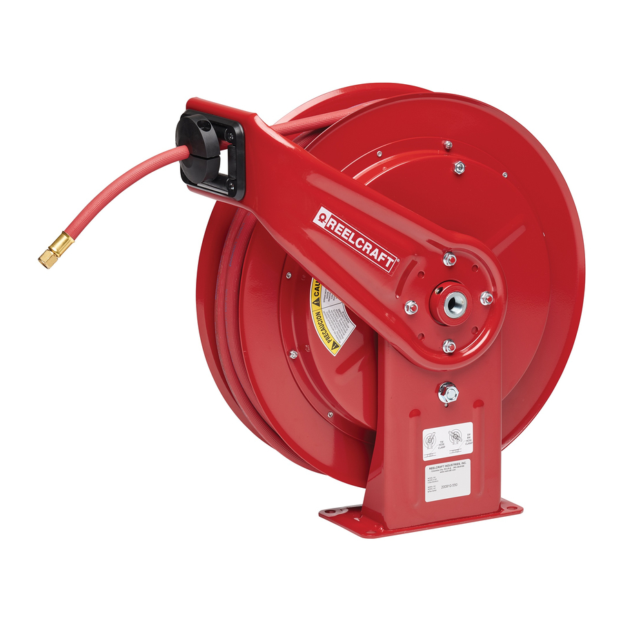
Welding Reels - Condensed Version
Series SW
Series TW
Safety
1.
Ensure that the reel is properly installed before
connecting input/output hoses or to power sup-
ply.
2.
Bleed fluid/gas pressure from system and dis-
connect all power before servicing the reel.
3.
Before connecting reel to supply line, ensure
that pressure/voltage/amperage does not exceed
maximum working pressure/voltage/amperage
rating of the reel.
4.
Ensure that the reel, hose/cord and equipment
being serviced are properly grounded. Use an
ohmmeter to check ground continuity.
5.
Pull hose/cord from reel by grasping the hose/
cord itself, not the work device.
6.
A high tension spring assembly is contained
within the reel. Exercise extreme caution.
7.
If reel ceases to unwind or rewind, remove sys-
tem pressure/power immediately. Do not pull or
jerk excessively on hose/cord!
8.
Treat and respect the reel as any other piece of
machinery, observing all common safety prac-
tices.
9.
If a leak/electrical malfunction occurs in the
hose or reel, remove system pressure/power
immediately.
10. Remember, even low pressure/low voltage is
very dangerous and can cause personal injury
or death.
11. Exercise extreme caution.
12. Check for faulty supply wires or hoses before
operating.
13. CAUTION: Do not shut off the fuel gas at the
regulator or supply source first, as a flashback
may result, and thereby damage the hose. Shut
off the gas at the torch first, and then at the regu-
lator or supply source, to limit permeation of
gas through the hose wall. This should be done
when the torch will not be used for periods in
excess of 30 minutes.
14. After the flame has been extinguished and the
gas turned off at the supply source, it is rec-
ommended that any remaining gas be bled to
minimize degradation of the rubber during long
shutdowns.
15. To prevent an accumulation or concentration of
gas that could be explosive or otherwise harmful
to personnel, adequate ventilation must be pro-
vided at all times, particularly in confined areas
where fuel gas is being used.
Reelcraft Industries, Inc. • 2842 E Business Hwy 30, Columbia City, IN 46725
Ph: 800-444-3134 / 260-248-8188 • Fax: 800-444-4587 / 260-248-2605
Customer Service: 855-634-9109 • reelcraft@reelcraft.com • www.reelcraft.com
Series WC
Series BA
Installation
For cable reels, ensure that only a qualified electrician
installs/services equipment. Observe applicable NEC,
OSHA, and local electrical codes when installing this
equipment. Unless reel was specified differently when
ordering, maximum installation height is 16 feet. Do
not exceed this distance.
Mounting & Guide Arm
Adjustment
The reel is equipped for universal mounting so that
it can be mounted on a structurally sound floor, wall
or ceiling; whichever provides maximum performance.
The guide arm on spring driven reels must be rotated
to a position that allows the hose/cord to feed through
the roller brackets with minimal bending. Replace the
fasteners. Where applicable, the U-Bolt, which fastens
hose to spool, must be placed in the proper loca-
tion when rotating the guide arm, otherwise the reel
might "latch out" during use. Refer to online manual
for proper U-Bolt locations. Position reel to mount-
ing surface and secure into place, using four secure
fasteners (not included).
Install the Output Cord
(Series WC)
1.
Remove the three outer nuts on the collector ring
cover and remove the cover.
2.
Strip 1 1/8" of insulation from the output cord
and insert cord around the reel spool (not
through the guide arm opening).
3.
Add protective tubing around opening in spool.
4.
(Series WC7000) Route the cord through the
opening in the spool, through the opening in
the collector ring base casting, then through
the strain relief until cord is between 2 clamp
plates. Tighten clamp plate fasteners until the
cord is securely captured between the plates;
tighten strain relief. (Series WC80000) Route
cord through the opening in the spool, through
the strain relief, through the main shaft and then
capture cord at end of collector ring with set-
screw. Fasten strain relief to the main shaft and
tighten cord with strain relief.
5.
Replace the collector ring with 3 outer nuts.
6.
Fasten cord to spool by capturing with U-Bolt.
Fasten to spool with nuts/washers supplied.
7.
Wrap all of the cord around the spool.
8.
Once cord is on the spool, add additional turns
Read these instructions carefully before attempting to install, operate, or
maintain your reel. Only qualified persons should install this product.
Failure to comply with instructions may result in personal injury and/
or property damage. Every attempt is made to ensure the accuracy and
completion of these instructions; however, Reelcraft is not responsible for
ommissions. To obtain the complete version of Reelcraft's service manu-
als, technical bulletins, and other support, please visit www.reelcraft.com
or call customer service during business hours.
9.
10. Use an ohmmeter, check for ground faults.
CAUTION: Use extreme caution; reel under tension.
Avoid releasing the latch mechanism. Apply Teflon
tape to inlet/outlet connections. Refer to page 4 for
inlet hose connection instructional drawings.
1.
2.
3.
CAUTION: Remove supply line pressure before
performing the following procedure.
1.
2.
3.
CAUTION: Use extreme caution; reel under tension.
Avoid releasing latch mechanism.
1.
2.
User servicing of the reel is limited to replacing the
hoses/cords or swivel only. Refer all other repairs
directly to the manufacturer. Failure to do so can re-
sult in personal injury and/or equipment damage and
may void the warranty.
to add tension (2-3 should be sufficient).
Add cord bumper stop at desired location.
Install/Replace the Hose
(Series SW/TW)
Manually turn spool assembly until spring is
tight, back off three turns then latch.
Route output hose(s) through guide bracket.
Using a wrench, firmly hold onto output
fitting(s) on swivel (Series 5000, 7000 & 70000)
or fitting(s) on shaft (Series 30000 & 80000)
while tightening the hose connector.
Replace the Swivel
Remove supply line from swivel.
Remove swivel assembly from inlet shaft.
Apply thread sealant to threaded connection and
re-install swivel assembly to inlet shaft by re-
versing steps 1 and 2.
Adjust the Reel
If necessary, adjust spring tension of reel by
adding/removing wraps of hose/cord from
spool, one at a time, until desired tension is
obtained.
Add wraps to increase tension. Remove wraps
to decrease tension. CAUTION: When adding
wraps of hose/cord, be careful not to exceed
the winding mechanisms spring capacity. Add
just enough wraps of hose/cord to achieve the
desired tension. Damage to the winding mecha-
nism will result if spring is over-tensioned.
Repairs
Form #400-908 Rev: 8/2020
Publicidad

Manuales relacionados para Reelcraft SW Serie


Resumen de contenidos para Reelcraft SW Serie
- Página 1 Once cord is on the spool, add additional turns Form #400-908 Rev: 8/2020 Reelcraft Industries, Inc. • 2842 E Business Hwy 30, Columbia City, IN 46725 Ph: 800-444-3134 / 260-248-8188 • Fax: 800-444-4587 / 260-248-2605 Customer Service: 855-634-9109 • reelcraft@reelcraft.com • www.reelcraft.com...
- Página 2 Para obtener la versión completa de los manuales de servicio, visite www.reelcraft.com o llame a Servicio al Cliente en horario Serie SW...
- Página 3 Dérouleurs de Soudage - Version condensée nous dégageons notre responsabilité de constructeur en cas d’éventuelles omissions. Pour obtenir la version complète des manuels de service de Reelcraft, veuillez visiter le site www.reelcraft.com, ou appeler notre assistance à la clientèle pendant les heures Série SW...
- Página 4 (verde) 6.4 mm (1/4”) Reelcraft offre une garantie limitée de deux ans sur la plupart des produits. Le fait de ne pas FPT (roja) Arrivée installer ou entretenir les produits conformément au manuel de service peut annuler la garantie.