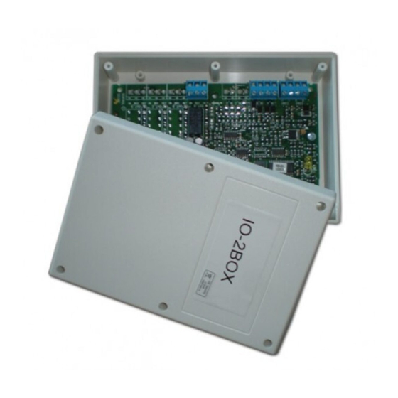
Resumen de contenidos para Aritech IO2000C Serie
- Página 1 IO2000C Series I/O Modules Installation Sheet EN DA DE ES FR NL PL PT RU SV © 2013 UTC Fire & Security. All rights reserved. 1 / 16 P/N 55370161 • REV 05 • ISS 30OCT13...
-
Página 2: En: Installation Sheet
Wiring EN: Installation Sheet Connect the I/O module to the loop via the COM2 (positive) and COM1 (negative) inputs. Description Inputs A to D each require an end-of-line resistor (150KΩ, 5%, 1/4W). Inputs are supervised for open circuit (ON/OFF) or This document includes installation information for the short circuit (ON/OFF) status. -
Página 3: Da: Installations Vejledning
Optional resistor for supervised 33KΩ, 5%, 1/4W Modul Indgange Udgange inputs IO2032C −5 to +40°C Operating temperature IO2034C −20 to +60°C Storage temperature Relative humidity 10 to 95% Installation (noncondensing) Dimensions 175 × 124 × 51 mm Modullayout Weight 100 g Figur 2 viser: Fejl-LED eller kortslutning af overvågede indgange Regulatory information... -
Página 4: Tekniske Specifikationer
Tekniske specifikationer Tabelle 1: Verfügbare Ein- und Ausgänge Modul Eingänge Ausgänge Driftsspænding 17 til 39 V DC Strømforbrug (standby): IO2014C 420 µA IO2014C / IO2034C maks. 350 µA IO2031C IO2014C / IO2034C typisk < 350 µA IO2031C / IO2032C maks. IO2032C <... -
Página 5: Instalación
Wartung • IO2014C (4 entradas) • IO2031C (2 entradas / 1 salida) Die grundlegende Wartung reduziert sich auf eine jährliche • IO2032C (2 entradas / 2 salidas) Prüfung. Interne Leitungen oder Schaltkreise nicht verändern. • IO2034C (4 entradas / 4 salidas) Technische Daten Entradas y salidas disponibles Las entradas y salidas disponibles para cada módulo están... -
Página 6: Mantenimiento
Nota: Para solucionar los posibles efectos en la mecánica del FR: Instructions d'installations envío y almacenamiento le recomendamos que primero gire cada marcador en el sentido contrario a las agujas del reloj (hasta la posición 0) y, a continuación, los gire en el sentido de las agujas del reloj (hasta la posición máxima de cada Description marcador) antes de configurar la dirección oportuna. -
Página 7: Spécifications Techniques
Impédance de la boucle Etat du module Fabricante Gulf Security Technology Co.,Ltd d’entrée* 80, Changjiang East Road, QETDZ, Qinhuangdao, 5.6KΩ – court-circuit Court (court-circuit) Hebei Province, China 066004 * 150KΩ résistance fin de ligne incluse Représentant européen de la fabrication: UTC Fire &... -
Página 8: Nl: Installatie Instructies
Tabella 2: Impedenza e stato del dispositivo Uso previsto Vedere punto 3 della dichiarazione DoP Impedenza circuito di ingresso* Stato del dispositivo Caratteristiche essenziali Vedere punto 9 della dichiarazione DoP Circuito aperto - 555KΩ Aperto (circuito aperto) Fabbricante Gulf Security Technology Co.,Ltd 80, Changjiang East Road, 243KΩ... -
Página 9: Technische Specificaties
(AAN.UIT) of kortsluiting (AAN/UIT). Voor een volledig Productidentificatie IO2014C, IO2031C, IO2032C, IO2034C bewaakte ingang (open contact en kortsluiting) moet een extra Beoogde gebruik Zie punt 3 van de verklaring van prestatie weerstand (33KΩ, 5%, 1/4W) worden geplaatst, zoals nummer weergegeven in Figuur 3. Essentiële kenmerken Zie punt 9 van de verklaring van prestatie nummer... -
Página 10: Parametry Techniczne
Wejścia A–D wymagają rezystora końcowego (150 KΩ, 5%, Certyfikaty i normy 1/4 W). Wejścia są monitorowane pod kątem rozwarcia (WŁ./WYŁ.) lub zwarcia (WŁ./WYŁ.). W całkowicie Ta sekcja zawiera zarówno informacje prawne, jak i podsumowanie dotyczące deklarowanych właściwości zgodnie nadzorowanym wejściu (rozwarcie i zwarcie) jest niezbędny z rozporządzeniem CPR 305/2011. - Página 11 Instalação Resistência de linha < 100Ω Resistência fim-de-linha 150KΩ, 5%, 1/4W Esquema dos módulos 33KΩ, 5%, 1/4W Resistência opcional para entradas supervisionadas Figura 2 indica: −5 a +40°C Temperatura de operação LED de falha para circuitos abertos ou curto-circuitos nas −20 a +60°C Temperatura de armazenamento entradas supervisionadas...
-
Página 12: Технические Характеристики
Установка Технические характеристики Схема модуля Рабочее напряжение от 17 до 39 В (постоянное напряжение) На рисунке 2 показано: потребление тока (в режиме Светодиодный индикатор для уведомления о коротком ожидания): IO2014C / IO2034C Макс. 420 µA замыкании или размыкании сети на контролируемых 350 µA входах... - Página 13 Adressering SV: Installationsanvisnin Varje I/O modul måste tilldelas en adress från 1 till 128. Använd den roterande nummerskivan märkt 0-12 för att ange Beskrivning tiondel och hundradel för adressen och den roterande nummerskivan märkt 0 till 9 för återstående siffror. Se Figur 4 Det här dokumentet innehåller installationsinformation för för olika exempel på...
- Página 14 14 / 16 P/N 55370161 • REV 05 • ISS 30OCT13...
- Página 15 P/N 55370161 • REV 05 • ISS 30OCT13 15 / 16...
- Página 16 16 / 16 P/N 55370161 • REV 05 • ISS 30OCT13...


