Publicidad
Idiomas disponibles
Idiomas disponibles
Enlaces rápidos
METERING AIR SYSTEM
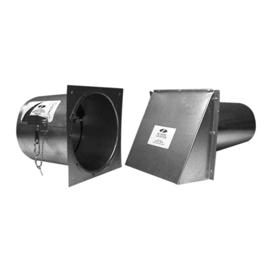
The Field Metering Air System consists of an intake air hood which is installed through the wall to
allow outside air in. The hood is connected via flexible 6" duct or standard duct pipe (not included) to
our metering air device mounted on the return/supply air plenum. This device effectively meters the
air inflow for proper air circulation, combustion and balance.
Model: MAS-1
I
TEMS INCLUDED
1)
Metering air damper
1)
Mounting template
1)
6" intake hood
20) Small washers (2 grams each)
3)
Large washers (50 grams each)
English ...... Page 1
Français..... Page 3
Espanõl ..... Page 4
Publicidad

Resumen de contenidos para Field Controls MAS-1
- Página 1 METERING AIR SYSTEM Model: MAS-1 The Field Metering Air System consists of an intake air hood which is installed through the wall to allow outside air in. The hood is connected via flexible 6” duct or standard duct pipe (not included) to our metering air device mounted on the return/supply air plenum.
-
Página 2: Installation And Adjustments
INSTALLATION AND ADJUSTMENTS 1. Apply mounting template onto the side of the return air plenum of the furnace. By wetting the back side and applying to any vertical surface of the return air plenum. CAUTION: Unit must be mounted on a vertical surface. Level the template horizontally by marking a line onto the plenum using a level. - Página 3 TABLE 1 AIRFLOW CHART APPROXIMATE CFM NUMBER OF ADJUSTMENT WEIGHTS ADDED BUILDING SQUARE FEET OF MAKE-UP SMALL LARGE GRAMS SUPPLIED TO PLENUM 1000 1250 1500 1750 2000 2250 2500 2750 3000 The cfm of make-up air was based on 1/2 air changes per hour in the building, an average ceiling height of 8 feet and a return air plenum pressure of .4 inches of water column.
- Página 4 INSTALLATION 1. Placer le gabarit de montage sur le côté du plenum de retour d’air de la fournaise. Mouiller le côté arrière et apposer sur toute surface verticale du plenum de retour d’air. ATTENTION: L’unité doit être installée sur une surface verticale. Mettre le gabarit horizontalement de niveau en traçant une ligne sur le plenum au moyen d’un niveau.
- Página 5 TABLEAU 1 DIAGRAMME DE FLUX D'AIR NOMBRE DE POIDS DE RÉGLAGE AJOUTÉS AIR D’APPOINT EN PI3/MIN BÂTIMENT, PIEDS CARRÉS ENVOYÉ AU PLENUM PETIT GROS GRAMMES 1000 1250 1500 1750 2000 2250 2500 2750 3000 L’air d’appoint en pi3/min est calculé selon un demi-changement d’air par heure dans le bâtiment, une hauteur de plafond moyenne de 8 pi et une pression au plenum de retour d’air de 0,4 po à...
-
Página 6: Instalación
INSTALACIÓN 1. Aplique la plantilla de montaje del lado del pleno del aire de recuperación del generador, humedeciendo la parte posterior y aplicándola a una superficie vertical del pleno de aire de recuperación. PRECAUCIÓN: La unidad debe colocarse sobre una superficie vertical. Nivele la plantilla horizontalmente marcando una línea sobre el pleno usando un nivel. - Página 7 Tabla 1 DIAGRAMME DE FLUX D'AIR NÚMERO DE PESOS DE AJUSTE PIES CÚBICOS POR MINUTO (CFM) PIES CUADRADOS DEL AGREGADOS APROXIMADOS DE COMPENSACIÓN EDIFICIO SUMINISTRADOS AL PLENO PEQUEÑAS GRANDES GRAMOS 1000 1250 1500 1750 2000 2250 2500 2750 3000 Los pies cúbicos por minuto de aire de compensación se basan en la mitad de cambios de aire por hora en el edificio, una altura promedio del techo de 8 pies y una presión del pleno de aire de recuperación de 0,4 pulgadas de columna de agua.
- Página 8 Page 8 P/N 46233500 Rev A 11/00...