Publicidad
Idiomas disponibles
Idiomas disponibles
Enlaces rápidos
VT 20M
Intermittent Fan Control
WARNING: Ensure that power is
switched off at service panel before
commencing installation.
WARNING: Main Control Unit must
not be installed where it can be
reached from a tub or a shower. Unit
must be installed on GFCI circuit if
located in bathroom.
Electrical wiring must be done by
qualified person(s) in accordance with
all applicable codes and standards.
NORMAL OPERATION
Main Control unit (VT20M) features both a timer and
speed control that will activate an exhaust fan at a
certain speed for a selected period of time each hour.
To select fan speed, adjust lover slide control to desired
speed. To select fan on-time, ajust upper slide control
to time desired (5 minute intervals). For example, if the
fan-on time (upper slide adjuster) is set at one quarter
from the bottom, the fan will run for 15 minutes every
hour at the preset speed (lower slide adjuster).
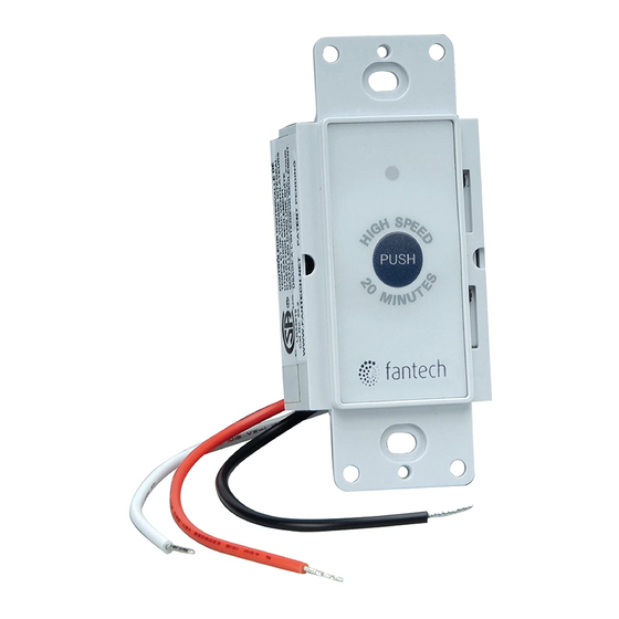
For temporary full speed onperation, press the button
on the front of the control (main or auxiliray). The fan
will run at full speed for 20 minutes and the resume
its normal preset cycle. Full speed is indicated by a
blue light illuminated on the front of the control panel.
To return to the normal cycle before 20 minutes had
elapsed, press and hold the button for five seconds.
DESCRIPTION
The Fantech intermittent Fan Control is designed to
be used with Fantech FG, FR, FQ and PB fans only to
meet whole-house ventilation needs as prescribed by
independent residential ventilation authorities such as
HVI and ASHRAE.
The model VT20M controller enables the fan to run at a
preset speed for a preset portion of each hour, 24 hours
a day everyday.
The high speed override button enables the fan to run at
full speed for 20 minutes wheh needed, for example to
vent steam from a bathroom.
SPECIFICATIONS
For control of 120V AC exhaust fans up to 2.5A.
Use only with 120V AC single phase electrical supply.
MAIN CONTROL UNIT
• Install in standard wall box prewired with LINE and
NEUTRAL.
• Using twist wire connectors, connect NEUTRAL to
both the WHITE wire on the main control unit and to
the NEUTRAL terminal on the remote fan.
• Connect LINE to the BLACK wire on the main control
unit.
• Connect the RED wire on the main control unit to the
LINE terminal on the remote fan. See wiring diagram
for more details.
• Screw the main control unit into the wall box so that it
is flush with the wall.
• Restore power at the service panel and push high
speed button to verify power to the remote fan.
• Adjust time and speed adjuster to deisred levels and
install the decorative wall plate.
The wall plate must be removed to make
adjustmnents to time and speed.
Item #: 407392
Rev Date: 2020-02-10
fantech
Publicidad

Resumen de contenidos para Fantech VT20M
- Página 1 WARNING: Ensure that power is The Fantech intermittent Fan Control is designed to switched off at service panel before be used with Fantech FG, FR, FQ and PB fans only to commencing installation. meet whole-house ventilation needs as prescribed by...
- Página 2 DESCRIPTION le courant électrique est Le contrôle intermittent pour ventilateurs FG, FR, FQ et débranché au panneau de PB seulement de Fantech a été conçu d’après les besoins service avant de commencer «Whole-House» prescrites par des personnes autorisées l’installation. indépendantes de la ventilation résidentielle comme HVI et AHRAE.
- Página 3 El Ventilador Control intermitent Fantech está diseñado para de eletricidad esté apagada en el usares con los ventiladores FG, FR, FQ y PB de Fantech fin de panel de servicio. satisface la necesidades de ventilación residencial, tales como ADVERTENCIA: Ni la Unidad de la HVI y la ASHRAE.
- Página 4 Neutral Ventilateur Neutre Ventilador Neutral White Line Blanc Ligne Blanco Línea Black Load Noir Charge Negro Carga Contacts: United States / États-Unis / Estades Unidos Americanos Canada / Canada / Canadá Tel.: 800.747.1762 • USsupport@fantech.net Tel.: 800.565.3548 • CANADAsupport@fantech.net fantech...
