Publicidad
Idiomas disponibles
Idiomas disponibles
Enlaces rápidos
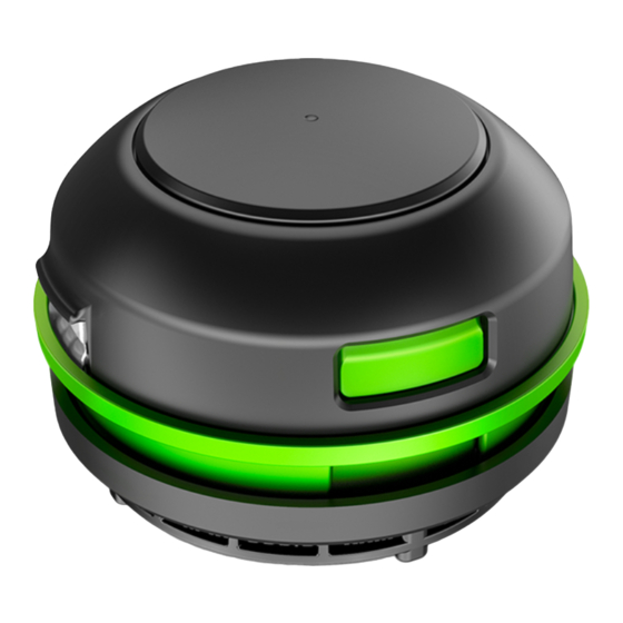
REPLACEMENT STRING TRIMMER HEAD
This Replacement String Trimmer Head is exclusively compatible with
EGO POWER+ String Trimmer ST1510T and ST1510T-FC.
DANGER:
If the head loosens after it is fixed in position, replace it immediately. Never use a trimmer
with a loose cutting attachment. Replace a cracked, damaged or worn out cutting head immediately, even
if damage is limited to superficial cracks. Such attachments may shatter at high speed and cause serious
injury.
WARNING:
Always remove the battery pack from the product when you are assembling parts,
making adjustments, cleaning, or when the product is not in use.
1
Bushing2#
Bushing1#
Washer
Upper Cover Base
Upper Cover
Spool Assembly
Cutting Line
REMOVE THE TRIMMER HEAD
1. Remove the battery pack from the trimmer.
2a
2b
Lower Cover
Assembly
Release Tab
3
2. Press the release tabs on the trimmer head
and remove the lower cover assembly of the
trimmer head by pulling it straight out (see
Fig. 2a & 2b).
3. Remove the cutting line from the trimmer
head (Fig. 3).
4. Remove the spring from the spool assembly,
if necessary. Save it for reassembly.
5. Wear gloves. Use one hand to grasp the spool
assembly to stabilize it, and use the other
hand to hold an impact wrench (not included) to loosen the nut in a counterclockwise direction (Fig. 4).
6. Remove the nut, washer, spool assembly, upper cover, bushing1# and Upper Cover Base, from the
motor shaft (Fig. 5).
Bushing2# easily fall off the motor shaft, so take care to save them for
NOTICE:
reassembly.
7. Replace with a new trimmer head and mount it in following steps.
4
OPERATING MANUAL
MODEL NUMBER AH1522
INSTALL THE NEW TRIMMER HEAD
1. Mount the bushing2# in motor shaft and
mount the Upper cover base assembly into
place (Fig. 6).
2. Mount the bushing 1#, upper cover, spool
assembly, washer and nut in that order. Use
an impact wrench on the nut to tighten it.
3. Insert the spring into the slot in the lower
cover assembly (Fig. 7).
4. With one hand holding the trimmer, use the
other hand to grasp the lower cover assembly and align the slots in the lower cover assembly with
Nut
the release tabs. Press the lower cover assembly until it snaps into place, at which time you will
Spring
Lower Cover
hear a distinct click sound (Fig. 8).
Assembly
5. Start the tool to see whether the string trimmer will work normally. If it does not, reassemble as
described above.
7
LINE REPLACEMENT
2
WARNING:
dangerous projectiles.
WARNING:
nylon cutting line with a diameter that does not
1
exceed 0.095 in. (2.4 mm). Using line other than
that specified may cause the tool to overheat or
become damaged.
The string trimmer is equipped with an advanced
POWERLOAD
system. The cutting line can
TM
be wound onto the spool simply by pressing a
single button. Loading a full spool can usually be
completed in 12 seconds. Avoid repeated operation
of the winding system in rapid succession to reduce
the possibility of motor damage.
1. Remove the battery pack from the trimmer.
2. Cut one piece of cutting line 13 ft. (4m) long.
3. Insert the line into the eyelet (Fig.9) and push
the line until the end of the line comes out of
the opposite eyelet.
NOTICE:
It is not necessary to align the eyelets
in order to insert the cutting line. If the line cannot
be inserted into the eyelet, mount the battery pack
onto the trimmer, then press the line-loading button
5
Bushing2#
Upper Cover
Bushing1#
Upper
Cover Base
6
Motor Shaft
8
Spring
Release Tab
Never use metal-reinforced line, wire, or rope, etc. These can break off and become
Always use the recommended
9
10
Isometric Cutting Line
briefly to release the lower cover.
4. Remove the battery if it has been mounted onto the trimmer in step 3.
5. Pull the line from the other side until equal lengths of the line appear on both sides of the trimmer
head(Fig. 10).
6. Install the battery pack onto the string trimmer.
7. Press and hold the line-loading button to
start the line-winding motor. The line will be
wound into the trimmer head continuously
(Fig. 11).
Spool Assembly
8. Watch the remaining line length carefully.
Prepare to release the button as soon as
approximately 7 inches (17.8cm) of line
Washer
are left on each side. Briefly press the line
loading button to adjust the length until 5.5
Nut
inches (14cm) of the line is showing on each
side.
9. Push down on the Lower Cover Assembly while pulling on the lines to manually advance the line in
order to check for proper assembly of the cutting line.
Bushing2#
Bushing1#
Slot
Cutting Line
Lower Cover
Eyelet
11
5.5" (14cm)
Publicidad

Resumen de contenidos para EGO AH1522
- Página 1 Prepare to release the button as soon as This Replacement String Trimmer Head is exclusively compatible with approximately 7 inches (17.8cm) of line Washer EGO POWER+ String Trimmer ST1510T and ST1510T-FC. are left on each side. Briefly press the line Upper DANGER: loading button to adjust the length until 5.5...
- Página 2 Cette tête de taille-bordure de rechange est compatible exclusivement avec les Rondelle 7. Appuyez sur le bouton de chargement du fil taille-bordure EGO POWER+ ST1510T et ST1510T-FC Base du cache pour mettre le moteur d’enroulement du fil en 14 cm / 5,5 po supérieur...
- Página 3 Este cabezal de orilladora de hilo de repuesto es compatible exclusivamente con la 5. Jale el hilo desde el otro lado hasta que aparezcan longitudes iguales del mismo a ambos lados del orilladora de hilo EGO POWER+ST1510T, ST1510T-FC Arandela cabezal de la orilladora (Fig. 10).