Tabla de contenido
Publicidad
Idiomas disponibles
Idiomas disponibles
Enlaces rápidos
Please read and save these instructions
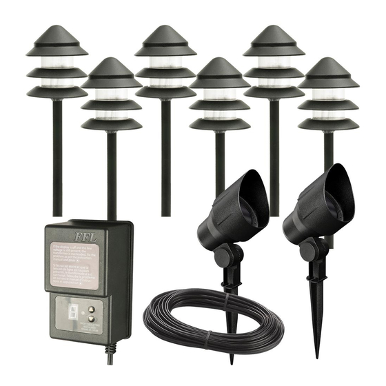
PACKAGE CONTENTS
G
H
K
I
L
J
M
Assembly and Installation
INSTRUCTIONS PERTAINING TO A RISK OF FIRE, OR INJURY TO PERSONS
IMPORTANT SAFETY INSTRUCTIONS
Lighted lamp is HOT!
CAUTION: Safe for outdoor operation
WARNING: To reduce the risk of FIRE OR INJURY TO PERSONS:
WARNING: Turn off/unplug and allow to cool before replacing lamp.
WARNING: Lamp gets HOT quickly! Contact only switch/plug when turning on.
Do not touch hot lens, guard or enclosure.
WARNING: Keep the lamp away from materials that may burn.
WARNING: Do not touch the lamp at any time. Use a soft cloth. Oil from skin may
damage the lamp.
WARNING: Do not operate the luminaire fitting with a missing or damaged lens
or bulb protector.
WARNING: Install in accordance with all local codes and ordinances.
Only for use with low voltage power units with a maximum output rating of 15V,
300W per secondary.
FOR LANDSCAPE LIGHTING SYSTEMS ONLY. OUTDOOR USE ONLY. THE DEVICE IS
ACCEPTED AS A COMPONENT OF A LANDSCAPE LIGHTING SYSTEM WHERE THE
SUITABILITY OF THE COMBINATION SHALL BE DETERMINED BY CSA OR LOCAL
INSPECTION AUTHORITIES HAVING JURISDICTION.
PATHLIGHT IS UL LISTED UNDER MODEL # GL22784
FLOODLIGHT IS UL LISTED UNDER MODEL # U201166
1
Attaching and installing the floodlight
WARNING: Never push the fixture into the ground by the lamp body (C) or use a
hammer to insert the spike (F) into the ground.
□
Carefully remove the fixture from its protective packaging.
□
Remove the lens cover (A) by turning counterclockwise.
□
Do not remove the lens from the lens cover.
□
Insert the bulb (B) into the bulb socket. Use a soft cloth, as oil from
skin may damage the lamp bulb.
□
Replace the lens cover (A) on the body (C) by turning clockwise.
□
Adjust the fixture's angle by loosening the adjustment screw (D)
and retightening it.
□
Ensure the lens points up and
never towards the ground.
C
A
B
D
E
N
F
A
B
D
LOW VOLTAGE PATHLIGHT AND FLOODLIGHT KIT
Part
Description
A
Lens cover
B
20W Halogen T3 Bi-Pin Bulb
C
Body
D
Adjustment screw
E
Connector
Q
O
F
Spike
G
Top cover
P
H
7W T5 WedgeBulb
2
Attaching and installing the pathlight
WARNING: Never push the fixture into the ground by the lamp body (G) or use a
hammer to insert the spike (M) into the ground.
□
Carefully remove the fixture from its protective packaging.
□
Pass the wire through the spike (M).
□
Fix both post sections (K) together by turning clockwise.
□
Attach the spike by pushing it into the lower post section.
□
Insert the bulb (H) into the bulb socket.
□
Attach the body by pushing the lens (I) onto the post.
□
Put the metal disks (J) on the lens by guiding them between the
ribs on the lens and turn clockwise to secure them.
□
Attach the cover (G) to the lens by turning clockwise.
3
Connecting the wires
WARNING: The wire connector (E) & (L) contacts have sharp edges for piercing
the main low voltage cable. To avoid injury, do not touch the metal contacts.
C
WARNING: Risk of Electric Shock. Install all luminaires 10 ft. (3.05 m) or more
from a pool, spa or fountain.
CAUTION: The wire from the low voltage power unit shall be 12-16 AWG type
underground low Energy Circuit Cable or SPT2W.
IMPORTANT:
• Protect the wiring by routing it in close proximity to the light fitting, or next to a
building structure such as a house or deck.
• The landscape wire and connector can also be hidden under stone or buried
under grass at a maximum depth of 6" (15.24 cm).
• Do not submerge fixture in water.
Item #1001 492 702
Model #HD28905
Use and Care Guide
Quantity
I
Lens
2
J
Tier
2
K
Post
2
L
Connector
2
M
Spike
2
N
120W Transformer
2
O
Wire AWG14 SPT2W 75'
6
P
Plastic anchor
6
Q
Screw
H
G
I
J
K
M
6
12
12
6
6
1
1
1
1
Publicidad
Tabla de contenido

Manuales relacionados para HAMPTON BAY HD28905


Resumen de contenidos para HAMPTON BAY HD28905
- Página 1 Item #1001 492 702 Model #HD28905 Use and Care Guide Please read and save these instructions LOW VOLTAGE PATHLIGHT AND FLOODLIGHT KIT PACKAGE CONTENTS Part Description Quantity Lens Lens cover Tier 20W Halogen T3 Bi-Pin Bulb Post Body Connector Adjustment screw...
-
Página 2: Installing The Transformer
Assembly and Installation (Continued) How to operate the transformer controls □ Place the wire connector (L) on opposite sides of the low voltage cable (O) where the fixture will be located. PHOTOCELL □ Align and fit the main low voltage cable (O) vertically to the This component reacts to light conditions. -
Página 3: Care And Cleaning
Care and Cleaning □ Clean the fixture with a soft, dry cloth. □ Do not use any cleaners with chemicals, solvents or harsh abrasives. Troubleshooting Problem Possible cause Solution The fixture will not • There is no power. • Check that the power is on. light •... - Página 4 Núm. de artículo 1001 492 702 Núm. de modelo HD28905 Guía de uso y cuidado Por favor, lea y guarde estas instrucciones. JUEGO DE LUZ DE PASILLO DE BAJO VOLTAJE Y REFLECTOR CONTENIDO DEL PAQUETE Pieza Descripción Cantidad Lentes Cubierta de los lentes...
-
Página 5: Instalación Del Transformador
Ensamblaje y Instalación (continuado) □ Coloque el conector del cable (L) en los lados opuestos del Cómo operar los controles de transformadores cable de baja tensión (O) en la que se encuentra el aparato. FOTOCELULA □ Alinear y colocar el cable de baja tensión principal (O) Este componente reacciona a las condiciones de luz. -
Página 6: Cuidado Y Limpieza
Cuidado y limpieza □ Limpie el aparato con un paño suave y seco. □ No utilice productos de limpieza con productos químicos, disolventes o abrasivos. Resolución de fallas Problema Causa posible Solución • No hay poder. • Compruebe que la unidad está encendida. El dispositivo no se enciende •...