Tabla de contenido
Publicidad
Idiomas disponibles
Idiomas disponibles
Enlaces rápidos
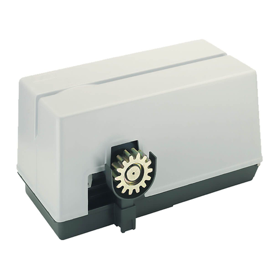
SUPER 3600
Operatore
Operateur
Operator
Torantrieb
Operador
SUPER 3600
SUPER 3600 ICE
Die korrekte Bedienung des Bedieners ist nur gewährleistet, wenn er von einem RIB-Bedienpanel verwaltet wird
ITALIANO pag. 05 / FRANÇAIS pag. 17 / ENGLISH page 29/ DEUTSCH pag. 41 / ESPAÑOL pag. 53
Alimentazione
Peso max cancello
Alimentation
Poids maxi portail
Power Supply
Max gate weight
Stromspannung
Max Torgewicht
Alimentacion
Peso máx verja
230V 50/60 Hz
3600 kg
Il corretto funzionamento dell'operatore è garantito solo se viene gestito da un quadro di comando RIB
Le bon fonctionnement de l'opérateur n'est garanti que s'il est géré par un panneau de contrôle RIB
The correct operation of the operator is guaranteed only if it is managed by a RIB control panel
El funcionamiento correcto del operador solo está garantizado si está gestionado por un panel de control RIB
con / avec / with / mit
L1/R2-CRX
Disegni tecnici per progetti
Dessins techniques pour les projets
Technical drawings for projects
Technische Zeichnungen für Projekte
Dibujos técnicos para proyectos.
Spinta max
Coppia max
Poussée maxi
Couple maxi
Max Thrust
Max torque
Max Schubkraft
Max. Drehmoment
Max Empuje
Coppia max
4700/4150 N
200/175 Nm
Vedere pagina 15
Voir page 27
See page 39
Siehe Seite 51
Ver página 63
Codice
Code
Code
Code
Codigo
AA31020
AA31024
Publicidad
Tabla de contenido

Manuales relacionados para RIB SUPER 3600 L1-CRX

Resumen de contenidos para RIB SUPER 3600 L1-CRX
- Página 1 Le bon fonctionnement de l’opérateur n’est garanti que s’il est géré par un panneau de contrôle RIB The correct operation of the operator is guaranteed only if it is managed by a RIB control panel Die korrekte Bedienung des Bedieners ist nur gewährleistet, wenn er von einem RIB-Bedienpanel verwaltet wird El funcionamiento correcto del operador solo está...
- Página 2 2° - En ce qui concerne la section et le type des câbles, RIB conseille d’utiliser un câble de 2° - Per la sezione ed il tipo dei cavi la RIB consiglia di utilizzare un cavo di tipo H05RN-F con type H05RN-F ayant une section minumum de 1,5 mm 2 et de toute façon, s’en tenir à...
- Página 3 Kontaktöffnung von 3 mm), der ein von den internationalen Normen 2° - For the section and the type of the cables RIB advices to use a cable of H05RN-F type anerkanntes Konformitätszeichen besitzt. Solch ein Geraet muss vor Vandalismus with 1,5 sqmm minimum section and, however, to keep to the IEC 364 and installation geschuetzt werden (z.B.mit einen Schluesselkatsten in einem Panzergehaeuse).
-
Página 4: Instalación
L’eliminazione dei materiali va fatta rispettando le norme vigenti. Non gettate il vostro 2° - Para la sección y el tipo de los cables, RIB aconseja utilizar cables de tipo H05RN-F con apparecchio scartato, le pile o le batterie usate nei rifiuti domestici. Avete la responsabilità di sección mínima de 1,5 mm 2 e igualmente atenerse a la norma IEC 364 y a las normas de... - Página 5 LAYOUT IMPIANTO A - Operatore SUPER 3600 B - Fotocellule esterne C - Cremagliera Modulo 6 D - Selettore a chiave E - Antenna radio F - Lampeggiatore H - Colonnina portafotocellula I - Fotocellula per protezione interna L - Costa meccanica M - Costa meccanica o elettrica con trasmettitore RED CARATTERISTICHE TECNICHE SUPER 3600...
- Página 6 INSTALLAZIONE SUPER 3600 CONTROLLO PRE-INSTALLAZIONE - IL CANCELLO DEVE MUOVERSI SENZA ATTRITI - N.B. È obbligatorio uniformare le caratteristiche del cancello alle norme e leggi vigenti. La porta può essere automatizzata solo se in buono stato e se rispondente alla norma EN 12604.
- Página 7 FISSAGGIO MOTORE E CREMAGLIERA La cremagliera va fissata a una certa altezza rispetto alla piastra di fissaggio del motore. Questa altezza può essere variata grazie a delle asole presenti sulla cremagliera. La registrazione in altezza viene fatta affinché il cancello durante il movimento, non si appoggi sull’ingranaggio di trazione del riduttore (Fig.
-
Página 8: Collegamenti Elettrici
COLLEGAMENTI ELETTRICI L1 cod. AC08082 Manuali online interattivi Manuels interactifs en ligne Interactive online manuals Interaktive Online-Handbücher Manuales interactivos en línea. - Página 9 RADIO Connettore per modulo radio ACG8069 Negativo alimentazione accessori a 24 Vdc RADIO Connettore per radio ricevitore rib ad innesto con alimentazione a 24 Vdc. A+ TEST Positivo per alimentazione autotest fotocellule a 24 Vdc Antenna radio 433 MHz COM A+ Comune dei contatti / Positivo 24 Vdc PROG.
- Página 10 B - SETTAGGI START Comando impulso singolo (verde) CLOSE Comando Chiude (verde) OPEN Comando Apre (verde) DIP 1 (ON) - CONTROLLO PER MANUTENZIONE (PAG. 13) DIP 2 (ON) - PROGRAMMAZIONE TEMPI (PUNTO C) PROBE DIP 2-1 PROGRAMMAZIONE TEMPI APERTURA PEDONALE (PUNTO D) NON DISPONIBILE DIP 1-2 MEMORIZZAZIONE/CANCELLAZIONE CODICI RADIO COMANDO APERTURA TOTALE (DIP 1...
- Página 11 DIP 6 OFF => Esegue l’apertura a cancello chiuso. Se azionato durante il movimento di Tramite App RIB GATE è possibile configurare il funzionamento di questo relé a piacere. apertura non ha effetto. Se azionato a cancello aperto lo chiude e durante la La programmazione può...
-
Página 12: Caratteristiche Tecniche
le colonnine di supporto alle fotocellule al morsetto A - per proteggere le fotocellule da fonti Ha il compito di segnalare quando il cancello è aperto, parzialmente aperto o comunque non di disturbo. chiuso totalmente. Si spegne solo quando il cancello è completamente chiuso. Fate attenzione a non creare corto circuiti quando le fasi di alimentazione sono invertite! Durante l’apertura lampeggia lentamente. - Página 13 eseguire il ponticello fra COM A+ e EDGE 1/EDGE 2) DL13 blu acceso Alcune funzioni sono abilitate tramite smartphone, verificare quindi tramite smartphone lo stato della scheda in quanto lo stato dei dip/ trimmer potrebbe essere non veritiero. Sulla scheda esistono dei fusibili ripristinabili che intervengono in caso di corto circuito interrompendo l'uscita a loro assegnata.
-
Página 14: Telecomando Sun
DIFETTO SOLUZIONE Sulla scheda esistono dei fusibili ripristinabili che intervengono in caso di corto circuito interrompendo l'uscita a loro assegnata. A fronte di una ricerca guasti si consiglia di scollegare tutti i connettori estraibili e di inserirli uno a Dopo aver effettuato i vari collegamenti e aver dato tensione, tutti i led sono spenti. volta in modo da identificare più... - Página 15 APP8054 Scheda APP+ APP8050 Scheda APP per gestire la centrale di comando per gestire la centrale di comando tramite Bluetooth tramite Bluetooth APP8064 Modulo Wi-Fi per Scheda APP8066 Modulo RJ45 per Scheda APP+ APP+ per gestire la centrale tramite rete per gestire la centrale tramite rete Wi-Fi locale (WLAN) dati locale (LAN)
- Página 16 RED permette la realizzazione di un impianto con coste fissate anche sull’anta in movimento senza l’adozione di sistemi raccogli cavo. È conforme alla norma EN13849-1:2007 e congiuntamente ad un quadro elettronico RIB è un dispositivo di protezione di Classe 2.
-
Página 17: Caractéristiques Techniques
SCHÉMA DÉTAILLÉ DE L’INSTALLATION A - Operateur SUPER 3600 B - Photocellules p/protec. externe C - Cremaillere m6 D - Selecteur E - Antenne radio F - Signal electrique H - Poteau zingué p/cellule ne I - Photocellules p/protection interne L - Barre palpeuse mécanique fixé... - Página 18 INSTALLATION SUPER 3600 CONTRÔLE PRÉ-INSTALLATION !! LE PORTAIL DOIT SE DÉPLACER SANS FROTTER !! N.B.: Il est impératif d’uniformiser les caractéristiques du portail avec les normes et les lois en vigueur. La porte peut être automatisée seulement si elle est en bon état et qu’elle est conforme à...
-
Página 19: Reglage Fin De Course
INSTALLATION DU MOTOR E DE LA CREMAILLERE La crémaillère doit être fixée à une certaine hauteur par rapport à la base du moteur. Cette hauteur peut être modifiée grâce à des boutonnières qui sont présentes sur la crémaillère. Le réglage en hauteur est effectué afin que le portail ne s’appuie pas sur l’engrenage de traction du réducteur (Fig. -
Página 20: Branchements Électriques
BRANCHEMENTS ÉLECTRIQUES L1 code AC08082 Manuali online interattivi Manuels interactifs en ligne Interactive online manuals Interaktive Online-Handbücher Manuales interactivos en línea. - Página 21 A - BRANCHEMENTS PROG IL EST OBLIGATOIRE DE INSTAURER LA FICHE AVEC DIP 13 EN POSITION “ON”. POWER 230 VAC MOTOR CAPACITOR L1 - N Alimentation 230 Vca 50/60 Hz (120 V 60 Hz sur demande) PROBE PAS DISPONIBLE Clignotant (max 40 W) ENCODER PAS DISPONIBLE Connexion commun du moteur...
- Página 22 B - RÉGLAGES DL14 Encodeur active (rosso) DL15 Commande PROG et RADIO sur molex (vert) DIP 1 CONTRÔLE D’ENTRETIEN (PAGE 25) (ON) B.I.O. Commande de horloge (vert) DIP 2 PROGRAMMATION DE LA DURÉE (ON) (POINT C) PED. Commande ouverture piétonne (vert) DIP 2-1 PROGRAMMATION DES LAPS DE TEMPS D’OUVERTURE POUR PIÉTONS (DIP 2 ON suivi de START Commande impulsif...
- Página 23 S’il est actionné à portail ouvert piéton, il Grâce à l’application RIB GATE, il est possible de configurer le fonctionnement de ce relais à le ferme. Si actionné pendant la fermeture, il rouvre le portail.
-
Página 24: Solution Des Problemes
(avec reprise du mouvement inverse après une seconde même si ces dernières demeurent occupées). FONCTION PRÉ-CLIGNOTEMENT DIP 5 OFF => Le moteur, le clignotant et le ronfleur partent simultanément. ATTENTION: Si la led du récepteur reste allumée, il est possible qu’ il y ait des perturbations DIP 5 ON =>... - Página 25 Si les leds ne s’allument pas, en maintenant toujours le portail en position intermédiaire, vérifier les points ci-après et éventuellement remplacer les composants qui ne fonctionnent pas. éteinte Bouton de STOP en panne (Dans le cas où le STOP n’est pas connecté, ponter entre COM A+ et STOP).
- Página 26 TABLEAU RÉCAPITULATIF ALARMES VISUELLES ET SONORES SIGNALISATIONS EN COURS DE PROGRAMMATION ÉVÉNEMENT ÉTAT BUZZER ÉTAT CLIGNOTEUR ÉTAT LED DL1 DIP 1 ON (mode homme mort) Éteint Éteint Clignote 250 ms ON/OFF Ou panne d'une sécurité DIP 2 ON (programmation course totale) Éteint Éteint Clignote 500 ms ON/OFF...
- Página 27 MODULE RADIO 433MHz EMETTEUR RADIO SUN cod. ACG8069 SUN 2CH cod. ACG6052 SUN 4CH cod. ACG6054 SUN CLONE 2CH cod. ACG6056 SUN CLONE 4CH cod. ACG6058 SUN-PRO 2CH cod. ACG6210 SUN-PRO 4CH cod. ACG6214 APP8054 Carte APP+ APP8050 Carte APP pour gérer le tableau de contrôle via pour gérer le tableau de contrôle via Bluetooth 4.2...
- Página 28 RED permet la réalisation d’une installation avec barres palpeuses fixées également sur le battant en mouvement sans l’adoption de systèmes d’assemblage de câbles. Il est conforme à la norme EN13849-1:2007 et associé à un tableau électronique RIB, il est un dispositif de protection de Classe 2.
-
Página 29: System Lay-Out
SYSTEM LAY-OUT A - SUPER 3600 operator B - Photoelectric cells (external) C - Rack M6 D - Key selector E - Tuned aerial F - Flashing lamp H - Galvanized column for P.E. cells I - Photo electric cells (internal) L - Safety strip fixed to column M - Mecanichal or electrical safety strip with RED transmitter TECHNICAL DATA... -
Página 30: Emergency Release
INSTALLATION SUPER 3600 CHECKING BEFORE THE INSTALLATION !! THE GATE SHALL MOVE FRICTIONLESS !! 2” N.B.: Gate features must be uniformed with the standards and laws in force. The door/gate can be automated only if it is in a good condition and its conditions comply with the BS EN 12604 norm. - Página 31 MOTOR AND RACK INSTALLATION The rack must be fixed at a certain height with respect to the motor base. This height can be varied thanks to the slots on the rack. The height needs to be adjusted so that the gate does not rest on the reduction unit traction gear (Fig.
-
Página 32: Electric Connections
ELECTRIC CONNECTIONS L1 code AC08082 Manuali online interattivi Manuels interactifs en ligne Interactive online manuals Interaktive Online-Handbücher Manuales interactivos en línea. - Página 33 + 24 Vdc accessories power supply / Common contacts RADIO Connector for radio module ACG8069 - 24 Vdc accessories power supply RADIO Connector for radio receiver RIB, 24 Vdc supply A+ TEST + 24 Vdc photocells self-test power supply 433 MHz Radio antenna COM A+ Common contacts / Positive 24 Vdc PROG.
- Página 34 POINT B - SETTINGS PROBE DIP 1 MAINTENANCE CHECK (See Page 36) IS NOT AVAILABLE DIP 2 PROGRAMMING (See Point C) DIP 2-1 PROGRAMMING OF PEDESTRIAN OPENING (See Point D) POINT C - TIMES PROGRAMMING DIP 1-2 SAVE/DELETE RADIO CODES FOR COMPLETE OPENING (DIP 1 ON followed by DIP 2 ON) (POINT E) N.B .: During the programming the safety functions Coast, Photocells and Stop button are DIP 1-3...
- Página 35 Indication is visible only when gate is stationary. workers, emergencies in parking or residential areas and, temporarily, for moving operations). 1 - Set DIP 1 to ON and then DIP 2 to ON. By connecting a switch and/or a daily/weekly clock to COM A+/B.I.O., you can open and keep 2 - The LED DL12 flashes green 6 times when the memory is full (1000 codes).
- Página 36 If held when the gate is fully open (or partially when using the pedestrian control) automatic - ALL THE PUSH BUTTONS, INPUTS AND COMMANDS CONNECTED TO THE CONTROL BOARD MUST BE closing is temporarily deactivated (if activated by the TCA trimmer and LED DL11 on). It is CLEAN CONTACT.
- Página 37 TABLE SUMMARISING VISUAL AND SOUND ALARMS SIGNALS DURING PROGRAMMING SEQUENCE EVENT BUZZER STATUS FLASHER STATUS DL1 LED STATUS DIP 1 ON (hold-to-run mode) Flashes ON/OFF 250 ms Or failure of a safety device DIP 2 ON (full stroke programming) Flashes ON/OFF 500 ms DIP 2 ON >...
- Página 38 FAULT SOLUTION On the board there are resettable fuses which intervene in the event of a short circuit, interrupting the output assigned to them. In the event of troubleshooting, it is advisable to disconnect all the removable connectors and After having carried out the various connections and having supplied voltage, all the LEDS are insert them one at a time in order to more easily identify the cause of the fault.
- Página 39 ACCESSORIES - For the connections and the technical data of the optional equipments follow the relevant handbooks. APP8050 APP card APP8054 APP+ card to manage the control panel using to manage the control panel using Bluetooth 4.2 transmission Bluetooth 4.2 transmission APP8064 Wi-Fi module for APP+ card APP8066 RJ45 module for APP+ card to manage the control panel using the...
- Página 40 RED allows to make a system made with edges fixed to the moving shutter without having to use cable sleeving systems. It complies with EN13849-1:2007 Standard, if installed with an RIB Electronic Board it is a Class-2 Device. code ACG6202...
-
Página 41: Technische Eigenschaften
ANLAGEN LAY-OUT A - Torantrieb SUPER 3600 B - Photozelle Toraussenseitig C - Zahnstange M6 D - Schlusselschalter E - Antenne F - Blinkleuchte H - Verzinkte Metallsäule als Photozellentrager I - Photozelle - Torinnenseitig L - Sicherheitskontaktleiste auf dem Schiebetor M - Mechanische oder elektrische Sicherheitsanlage mit Handsender RED TECHNISCHE EIGENSCHAFTEN SUPER 3600... - Página 42 INSTALLATION SUPER 3600 VOR DER MONTAGE AUSZUFÜHRENDE ÜBERPRÜFUNGEN !! DAS TOR MUSS REIBUNGSFREI LAUFEN !! ANMERKUNG: Es ist erforderlich, die Charakteristiken des Tors an die geltenden Normen und Gesetze anzupassen. Das Tor kann nur automatisch Angeschlossen werden, wenn es in einem einwandfreien Zustand ist und der EN12604 entspricht. - Das Tor welches keine Gehfluegelfunktion hat,in diesem Fall ist es erforderlich das Tor mit der norm EN 12453 punkt 6.5.1 in Einklang zu bringen (z.B.
- Página 43 MOTORBEFESTIGUNG UND ZAHNSTANGE (Abb. 5-6) Die Zahnstange muß in bestimmten Abstand von der Verankerungsplatte befestigt werden. Die Zahnstange darf nicht angeschweißt, sondern nur mit Hilfe von Gewindeschrauben an dem Gittertor befestigt werden. Die Höheneinstellung soll verhindern, daß das Gittertor auf dem Antriebszahnrad des Antriebes aufliegt.
- Página 44 ELEKTROANSCHLÖÜSSE L1 Kode AC08082 Manuali online interattivi Manuels interactifs en ligne Interactive online manuals Interaktive Online-Handbücher Manuales interactivos en línea.
- Página 45 Positive Ladung für die Speisung der Zubehöre zu 24 Vdc RADIO Verbinder für Radio-Modul ACG8069 Negative Ladung für die Speisung der Zubehöre zu 24 Vdc Verbinder für Radioempfänger RIB Steckverbindung mit Speisung zu 24 RADIO A+ TEST Positive Ladung für die Speisung für Fotozellen Selbstkontrolle...
- Página 46 B - EINSTELLUNGEN PED. Fußgänger Öffnungsbefehl (NO) (Grün) START Einzelimpulsbefehl (NO) (Grün) DIP 1 WARTUNGSÜBERPRÜFUNG (SIEHE SEITE 49) CLOSE Befehl Schließen (NO) (Grün) DIP 2 ZEITPROGRAMMIERUNG (ON) (PUNKT C) OPEN Befehl Öffnung (NO) (Grün) DIP 2 - 1 ZEITPROGRAMMIERUNG ÖFFNUNG FUSSGÄNGER (DIP 2 ON GEFOLGT VON DIP 1 ON) (PUNKT D) PROBE DIP 1-2...
- Página 47 * Die Fernsteuerungsverwaltung kann nur mit der RIB GATE-App aktiviert werden. FUNKTIONSWEISE DER SICHERHEITSEINRICHTUNGEN R-AUX arbeitet normalerweise 3 Minuten lang als Zusatzbeleuchtung. Über die RIB GATE-App kann der Betrieb dieses Relais wie gewünscht konfiguriert werden. FOTOZELLE (COM A+/PHOT 1, COM A+/PHOT 2) Die Programmierung kann nur bei stehendem Tor erfolgen.
- Página 48 ÜBERWACHUNG DER FOTOZELLEN (A+ TEST/A-) SIGNAL - 24 Vdc ANZEIGELEUCHTE TOR GEÖFFNET (COM A+/SIGNAL-) Den Fotozellensender an A+ TEST/A- anschließen und DIP 7 auf ON stellen. Signalisiert, wenn das Tor OFFen, teilweise OFFen oder nicht vollständig geschlossen ist. Es wird Die Überwachung besteht aus einem Funktionstest der Fotozelle vor jeder Bewegung.
- Página 49 Überbrückungsdraht zwischen COM A+ und PHOTO 1/PHOTO 2 legen) DL9 oder DL10 AUS Konktatleisten Schaden (Falls die Rippe nicht angeschlossen ist einen Überbrückungsdraht zwischen COM A+ und EDGE 1/EDGE 2 legen) DL13 Blau AUF Einige Funktionen sind über das Smartphone aktiviert. Überprüfen Sie daher per Smartphone die Kartenfunktionen, da der DIP / TRIMMER- Status möglicherweise nicht zutrifft.
- Página 50 ÜBERSICHTSTABELLE DER VISUELLEN UND AKUSTISCHEN ALARMEN SIGNALISIERUNGEN WÄHREND DER PROGRAMMIERPHASE EREIGNIS STATUS BUZZER STATUS BLINKLEUCHTE STATUS LED DL 1 DIP 1 ON (“befehl gedrückt gehalten”-modus) Abgeschaltet Abgeschaltet Blinkt 250 ms ON/OFF oder defekt einer sicherheitsvorrichtung DIP 2 ON (laufprogrammierung ganz) Abgeschaltet Abgeschaltet Blinkt 500 ms ON/OFF...
- Página 51 FERNSENDER SUN RADIO-MODUL 433MHz SUN 2CH Kode ACG6052 SUN 4CH Kode ACG6054 Kode ACG8069 SUN CLONE 2CH Kode ACG6056 SUN CLONE 4CH Kode ACG6058 SUN-PRO 2CH Kode ACG6210 SUN-PRO 4CH Kode ACG6214 APP8050 APP-Karte APP8054 APP+-Karte um das Steuerung mit Bluetooth um das Steuerung mit Bluetooth 4.2-Übertragung zu verwalten 4.2-Übertragung zu verwalten...
- Página 52 RED erlaubt die Realisierung einer Anlage mit Kontaktleisten, die auch auf dem sich bewegenden Tor angebracht sein können, ohne dass man Kabelsammelsysteme benötigt. Entspricht der Norm EN13849-1:2007 und in Verbindung mit einer RIB - Schalttafel stellt es eine Schutzvorrichtung der Klasse 2 dar.
-
Página 53: Disposiciòn De La Instalaciòn
DISPOSICIÒN DE LA INSTALACIÒN A - Operador SUPER 3600 B - Fotocélulas externas C - Cremallera Módulo 4 D - Interruptor de llave E - Antena de radio F - Intermitente H - Columnas para las fotocélulas I - Fotocélulas internas L - Nervadura mecánica M - Nervadura mecànica o elèctrica con transmisor RED CARACTERÍSTICAS TÉCNICAS... -
Página 54: Instalación Super 3600
INSTALACIÓN SUPER 3600 CONTROL PRE-INSTALACIÓN ¡¡LA VERJA TIENE QUE MOVERSE SIN ROCES!! IMPORTANTE: Es obligatorio uniformar las características de la verja a las normas y leyes en vigor. La puerta puede ser automatizada sólo si se encuentra en buen estado y responde a la norma EN 12604. -
Página 55: Anclaje Motor Y Cremallera (Fig. 5-6)
ANCLAJE MOTOR Y CREMALLERA (Fig. 5-6) La cremallera se tiene que anclar a una determinada altura respecto al soporte del motor. Dicha altura se puede variar gracias a unos ojales presentes en la cremallera. El ajuste de la altura se efectúa para que la verja durante el movimiento no se apoye sobre el engranaje de tracción del K (Fig. -
Página 56: Conexiones Eléctricas
CONEXIONES ELÉCTRICAS L1 cód. AC08082 Manuali online interattivi Manuels interactifs en ligne Interactive online manuals Interaktive Online-Handbücher Manuales interactivos en línea. - Página 57 Positivo 24 Vdc / Común de los contactos RADIO Conector para módulo radio ACG8069 Negativo 24 Vdc para alimentación accesorios RADIO Conector para radio receptor RIB con alimentación de 24 Vdc A+ TEST Positivo 24 Vdc para alimentación autotest fotocélulas Antenna radio 433 MHz COM A+ Común de los contactos / Positivo 24 Vdc...
-
Página 58: Dip 1-3 Memorización/Cancelación Códigos De Radio Para Mando De Apertura
B - AJUSTES PED. Mando de apertura peatonal (NA) (verde) START Mando de impulso unico (NA) (verde) DIP 1 CONTROL DE MANTENIMIENTO (ON) (PÁGINA 61) CLOSE Mando de cierre (NA) (verde) DIP 2 PROGRAMACIÓN DE LOS TIEMPOS (ON) (PUNTO C) OPEN Mando de apertura (NA) (verde) DIP 2-1 PROGRAMACIÓN DE LOS TIEMPOS DE APERTURA PEATONAL (DIP 2 ON seguido por DIP 1... -
Página 59: Funcionamiento Accesorios De Mando
DIP 6 ON => Ejecute un mando cíclico de órdenes abre-stop-cierra-stop-abre etc. A través de la aplicación RIB GATE es posible configurar la operación de este relé como se DIP 6 OFF => Ejecute la apertura con cancela cerrada. Si se acciona durante el movimento de desee. -
Página 60: Cheque De Mantenimiento
fotocélulas y se ordena la apertura, la cancela se abre (durante la apertura las Nota: Este panel electrónico puede alimentar SÓLO INTERMITENTES CON CIRCUITO INTERMITENTE fotocélulas no intervendrán). Las fotocélulas intervendrán solo en fase de cierre (ACG7072) de 40 W máximo. (con restablecimiento del movimiento inverso después de un s aún cuando las FUNCIÓN PRE-INTERMITENCIA mismas estén ocupadas). - Página 61 posicionado el portón en posición intermedia, verifique el correcto encendido de los led rojos DL6, DL7, DL8, DL9 y DL10. En caso de falta de encendido de los led, siempre con el portón en posición intermedia, verifique lo que sigue y sustituya eventuales componentes averiados. apagado Mando de Stop averiado (en caso de que el Stop no está...
-
Página 62: Señalizaciones Durante El Funcionamiento
TABLA SINÓPTICA DE LAS ALARMAS VISUALES Y ACÚSTICAS SEÑALIZACIONES EN FASE DE PROGRAMACIÓN EVENTO ESTADO DE BUZZER ESTADO DE L'INTERMITENTE ESTADO LED DL1 DIP 1 ON (modo persona presente) Apagado Apagado Parpadea 250 ms ON/OFF O bien avería de un seguro (modo funciona siempre) DIP 2 ON (programación carrera total) Apagado Apagado... -
Página 63: Telemando Sun
MÓDULO RADIO 433MHz TELEMANDO SUN SUN 2CH cód. ACG6052 SUN 4CH cód. ACG6054 cod. ACG8069 SUN CLONE 2CH cód. ACG6056 SUN CLONE 4CH cód. ACG6058 SUN-PRO 2CH cód. ACG6210 SUN-PRO 4CH cód. ACG6214 APP8054 Tarjeta APP+ APP8050 Tarjeta APP para administrar la unidad de control para administrar la unidad de control a través de Bluetooth 4.2 a través de Bluetooth 4.2... - Página 64 RED permite realizar una instalación con costas colocadas incluso sobre la hoja en movimiento sin la adopción de sistemas recoge cables. Conforme a la norma EN13849-1:2007. Unido a un cuadro electrónico RIB es un dispositivo de protección de Clase 2.
- Página 65 COLLEGAMENTI FOTOCELLULE - CONNEXIONS PHOTOCELLULE - PHOTOCELLS CONNECTIONS FOTOZELLEN VERBINDUNGEN - CONEXIONES FOTOCÉLULAS 4 fotocellule FIT SLIM / FIT SYNCRO con autotest e sincronizzatore del segnale infrarosso 2 fotocellule FIT SLIM, FIT SYNCRO con autotest 4 photocellules FIT SLIM / FIT SYNCRO avec autotest et synchroniseur de signal infrarouge 2 photocellules FIT SLIM, FIT SYNCRO avec autotest 4 FIT SLIM / FIT SYNCRO photocells with self-test and infrared signal synchronizer 2 photocells FIT SLIM, FIT SYNCRO with self-test...
- Página 66 COLLEGAMENTI FOTOCELLULE - CONNEXIONS PHOTOCELLULE - PHOTOCELLS CONNECTIONS FOTOZELLEN VERBINDUNGEN - CONEXIONES FOTOCÉLULAS 4 fotocellule NOVA sincronizzate con autotest 4 photocellules NOVA synchronisées avec autotest 4 NOVA photocells synchronized with self-test 4 NOVA Photozellen synchronisiert mit Selbstkontrolle 4 fotocélulas NOVA sincronizadas con autotest PHOT1 PHOT2 A+ TEST COM A+...
- Página 67 SUPER 3600 BA03001 CVA1023 CTC1405 CCU6307 CME1063 CTC1044 CME8087 CME1034 CTC1409 CZM6008 CME5105 CTC1168 CTC1084 CME1998 CTC1127 CTC1101 BA00159 (230 V-50/60 Hz) CPL1119 CCU6207 BA03615 CME1079 CVA1361 CTC1126 CVA1391 CPL1020 Codice Denominazione Particolare CEL1433 Pressacavo CTC1101 Paraolio 35x62x10 ACG1080 Chiave per serratura carter CAL1437 Condensatore 50µF 470V CTC1126...
- Página 68 Dichiarazione di incorporazione per le quasi-macchine - Direttiva Macchine 2006/42/CE, Allegato II., B Déclaration d’incorporation pour les quasi-machines - Directive Machines 2006/42/CE, Annexe II, B Declaration of incorporation for partly completed machinery - Machinery Directive 2006/42/EC, Annex II., B UK Declaration of Conformity - Supply of Machinery (Safety) Regulations 2008 Einbauerklärung für unvollständige Maschinen - Maschinenrichtlinie 2006/42/EG, Anhang II, B Declaración de incorporación de una cuasi máquina - Directiva de Máquinas 2006/42/CE, Anexo II, B R.I.B.