Tabla de contenido
Publicidad
Idiomas disponibles
Idiomas disponibles
Enlaces rápidos
Publicidad
Capítulos
Tabla de contenido

Manuales relacionados para Gewiss System Serie

Resumen de contenidos para Gewiss System Serie
- Página 1 RIVELATORE DI GAS GPL LPG DETECTOR DÉTECTEUR DE PRÉSENCE DE BUTANE/PROPANE DETECTOR DE PRESENCIA DE GPL GASWARNMELDER FÜR FLÜSSIGGAS DETECTOR DE GAZ GPL Serie SYSTEM: GW 20 868 GW 21 868 Serie PLAYBUS: GW 30 520...
- Página 2 ATTENZIONE - IMPORTANTE • Ci congratuliamo con Lei per la scelta di prodotti Gewiss. I prodotti Gewiss sono costruiti con attente cure dei dettagli impiegando solo materiali di qualità elevata. I prodotti Gewiss le garantiranno nel tempo prestazioni ottimali. • L'installatore è pregato di consegnare questo libretto debitamente compilato all'utilizzatore finale invitandolo a prendere conoscenza di quanto contenuto.
-
Página 3: Tabla De Contenido
INDICE GENERALITÀ - Funzioni ......................ISTRUZIONE D’INSTALLAZIONE - Caratteristiche tecniche .................. - Logica applicativa ................... - Descrizione morsetti ..................- Schemi di collegamento .................. - Montaggio......................10 ISTRUZIONI D’IMPIEGO - Descrizione comandi ..................11 - Funzionamento ....................12 - Test di funzionamento ..................14 - Prescrizioni per un corretto impiego.............. -
Página 4: Generalità
GENERALITÀ Funzioni I rivelatori elettronici di gas della serie System-Playbus per applicazione domestica consentono: • di rivelare la presenza di gas combustibile. • di azionare, mediante un relè interno, un’elettrovalvola a riarmo manuale per intercettare l’erogazione del gas alla sorgente. •... -
Página 5: Istruzione D'installazione
ISTRUZIONI D INSTALLAZIONE Caratteristiche tecniche Rivelatore di gas con sensore* semiconduttore al biossido di stagno. Segnalazione acustico/luminosa di allarme. Relé in uscita con contatti di tipo ermetico per il comando di elettrovalvola intercettazione gas. DATI TECNICI • Alimentazione 12V ac/dc +10/-15% •... -
Página 6: Logica Applicativa
ISTRUZIONI D INSTALLAZIONE Logica applicativa CONSIGLI SUL POSIZIONAMENTO Installare i rivelatori per GPL a 30 cm max dal piano pavimento e da 1 a 4 metri dagli ap- parecchi a gas. min. 1 m - max 4 m min. 1 m - max 4 m... - Página 7 Logica applicativa Attenzione ! Non installare i rivelatori vicino ad apparecchi di cottura, lavelli, prese d’aria, dispositivi di riscaldamento e condizionamento, finestre e dispositivi di ventilazione e do- vunque le condizioni ambientali ne possano compromettere il buon funzionamento. Elettrovalvola Caldaia L’INSTALLAZIONE DEL RIVELATORE DI GAS NON ESONERA DALL’OSSERVANZA DI TUT- TE LE REGOLE RIGUARDANTI LE CARATTERISTICHE, L’INSTALLAZIONE E L’USO DEGLI APPARECCHI A GAS, LA VENTILAZIONE DEI LOCALI E LO SCARICO DEI PRODOTTI DEL-...
-
Página 8: Descrizione Morsetti
ISTRUZIONI D INSTALLAZIONE Descrizione morsetti Il rivelatore può essere collegato alla rete 230V - 50 Hz (qualora richiesto) tramite modulo di alimentazione 230V ac - 12V dc (GW 20 866 - GW 21 866 - GW 30 518) 2 3 4 L (+) 12V ac/dc N (-) -
Página 9: Schemi Di Collegamento
Schemi di collegamento Alimentazione del rivelatore e dell’elettrovalvola a 12V 2 3 4 12V ac/dc Valvola tipo NC Alimentazione del rivelatore e dell’elettrovalvola a 12V Valvola tipo NA 2 3 4 12V ac/dc Alimentazione del rivelatore e dell’elettrovalvola a 230V 1 2 3 Valvola tipo NA 2 3 4... -
Página 10: Montaggio
ISTRUZIONI D INSTALLAZIONE Montaggio Ad installazione compiuta l'installatore avrà cura di applicare l'etichetta prestampata contenuta nella confezione sul rivelatore come indicato in figura, sulla quale é indicata la data raccomandata di sostituzione del rivelatore stesso. Il rivelatore installato ha una durata di 5 anni dal momento in cui viene alimentato. -
Página 11: Istruzioni D'impiego
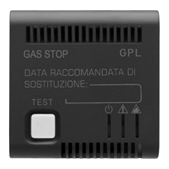
ISTRUZIONI D IMPIEGO Descrizione comandi Led giallo Segnalazione di guasto del dispositivo. Led rosso Segnalazione di allarme. Pulsante Led verde Attivazione Segnalazione procedura Test. presenza tensione rete. LEGENDA Led Acceso fisso Led Spento Led Lampeggiante... -
Página 12: Funzionamento
ISTRUZIONI D IMPIEGO Funzionamento Alla prima accensione il rivelatore, esegue la verde fase di inizializzazione, della durata di circa 60 secondi, durante la quale il dispositivo non è giallo operativo. Terminata la fase di inizializzazione il rivelatore verde è pronto al normale funzionamento. In caso di guasto del sensore del rivelatore il led verde verde ed il led giallo sono accesi fissi. - Página 13 Funzionamento Dispositivo in allarme. verde Istantaneamente al superamento della soglia di allarme i led verde e rosso si accendono e viene attivato l’avvisatore acustico. Dopo 20 secondi il relè commuta (comando elettrovalvola). rosso verde rosso A cessato allarme il rivelatore torna automaticamente allo stato di funzionamento normale.
-
Página 14: Test Di Funzionamento
ISTRUZIONI D IMPIEGO Test di funzionamento Premendo il tasto di Test, il buzzer si attiva (led verde rosso e verde accesi fissi). rosso Mantenendo premuto il tasto di Test per più di verde 20”, si ottiene anche la commutazione del relè (buzzer attivo, led verde e rosso accesi fissi). - Página 15 E N G L I S H LPG detector SYSTEM PLAYBUS...
- Página 16 ATTENTION IMPORTANT • Thank you for selecting this Gewiss product. Gewiss products have been designed with attention to detail and built using only the very best materials. Gewiss products will guarantee excellent and lasting performance. • The installer is kindly requested to fill out this leaflet and then hand it to the end user, asking that he/she carefully read it.
- Página 17 INDEX GENERAL DESCRIPTION - Functions ........................ 18 INSTALLATION INSTRUCTIONS - Technical features ....................19 - Application logic ..................... 20 - Terminals ........................ 22 - Wiring diagrams ...................... 23 - Assembly......................... 24 OPERATING INSTRUCTIONS - Description of the controls ..................25 - How it works......................
-
Página 18: General Description
GENERAL DESCRIPTION Functions System-Playbus electronic gas detectors for domestic use: • detect the presence of combustible gas • activate a solenoid valve via an internal circuit that cuts off the supply of gas at its source and must be manually reset •... -
Página 19: Installation Instructions
INSTALLATION INSTRUCTIONS Technical features Gas detector with tin dioxide semiconductor sensor*. Acoustic/luminous alarm signal. Output relay with hermetically sealed contacts that control the gas cut-off solenoid valve. TECHNICAL FEATURES • Power source 12V ac/dc +10/-15% • Electrical input • Alarm threshold 9% LIE (lower limit of esplosivity) •... -
Página 20: Application Logic
INSTALLATION INSTRUCTIONS Location advice ADVICE ON POSITIONING Install the LPG detectors at a maximum of 30cm from the floor and 1-4m from the gas devices. min. 1 m - max 4 m min. 1 m - max 4 m... - Página 21 Location advice Warning ! Do not install the detector near cooking appliances, sinks, air vents, heating and air conditioning equipment, windows, ventilation equipment, and anywhere room conditions could jeopardize the correct operation of the detector. Solenoid valve Boiler INSTALLING A GAS DETECTOR DOES NOT IN ANY WAY EXEMPT YOU FROM FOLLOWING ALL THE REGULATIONS REGARDING THE CHARACTERISTICS, INSTALLATION AND USE OF GAS APPLIANCES, ROOM VENTILATION, AND VENTING OF COMBUSTION PRODUCTS AS PROVIDED FOR BY THE UNI STANDARDS IN ACCORDANCE WITH THE LAW 1083/71...
-
Página 22: Terminals
INSTALLATION INSTRUCTIONS Terminals The detector can be connected to 230V - 50 Hz mains supply(if requested) by means of a 230V ac - 12V dc power supply module (GW 20 866 - GW 21 866 - GW 30 518) 2 3 4 L (+) 12V ac/dc N (-) -
Página 23: Wiring Diagrams
Wiring diagrams 12V power supply of the detector and solenoid valve 2 3 4 12V ac/dc NC valve 12V power supply of the detector and solenoid valve NO valve 2 3 4 12V ac/dc 230V power supply of the detector and solenoid valve 1 2 3 2 3 4 NO valve... -
Página 24: Assembly
INSTALLATION INSTRUCTIONS Assembly After installing the detector, the installer should attach the printed sticker on the detector in the pack as shown in the figure below. This sticker indicates the recommended date for replacement of the detector. Once installed and plugged in, the detector will last for 5 years. -
Página 25: Operating Instructions
OPERATING INSTRUCTIONS Description of the controls Yellow LED Indicates a fault in the device. Red LED Indicates alarm. Push-button Green LED Enables Test procedure. Indicates presence of mains voltage. Steady led on Led off Flashing led... -
Página 26: How It Works
OPERATING INSTRUCTIONS How it works The first time the detector is switched on, it green performs an initialization phase lasting 60 seconds during which the detector is not jellow operational. Once the initialization phase has ended, the green detector is ready for normal operation. If there is a fault in the detector sensor, the green green LED and the yellow LED are steady on. - Página 27 How it works Device alarm activated. green When the alarm threshold is exceeded the green and red LEDs instantly light up and the acoustic signal is activated. After 20 seconds the relay switches over (solenoid valve command). green When the alarm situation ends, the detector automatically returns to its normal operating mode.
-
Página 28: Test Procedure
OPERATING INSTRUCTIONS Test procedure By pressing the Test key, the buzzer is activated green (red and green LEDs steady on) By keeping the Test key down for more than 20 green seconds, the relay also switches over (buzzer activated, red and green LEDS steady on). Recommendations for proper use •... - Página 29 F R A N Ç A I S Détecteur de présence de butane/propane SYSTEM - PLAYBUS...
- Página 30 ATTENTION - IMPORTANT • Nos félicitations! Vous avez choisi des produits Gewiss. Les produits Gewiss sont construits avec un très grand soin dans les détails et en employant exclusivement des matériaux de première qualité. Les produits Gewiss vous garantiront dans le temps des prestations optimales.
- Página 31 INDEX GENERALITES - Fonctions ......................32 ISTRUZIONE D’INSTALLAZIONE - Caractéristiques techniques ..................33 - Logique applicative ....................34 - Description des bornes.................... 36 - Schémas de connexion ..................37 - Montage........................38 INSTRUCTIONS POUR L’EMPLOI - Description des commandes .................. 39 - Fonctionnement .....................
-
Página 32: Fonctions
GENERALITES Fonctions Les détecteurs électroniques de butane/propane de la série System-Playbus pour application domestique permettent: • de relever la présence de butane/propane. • d'actionner, grâce à un relais interne, une électrovalve à réarmement manuel pour intercepter le débit du butane/propane à la source. •... -
Página 33: Caractéristiques Techniques
INSTRUCTIONS POUR L INSTALLATION Caracteristiques techniques Détecteur de butane/propane avec capteur* à semi-conducteur au dioxyde d’étain. Signalisation d’alarme acoustique/lumineuse. Relais du sortie avec contact hermétiques pour le commande du électrovalve du interception de butane/propane DONNEES TECHNIQUES • Alimentation 12V ac/dc +10/-15% •... -
Página 34: Logique Applicative
INSTRUCTIONS POUR L INSTALLATION Logique d’application CONSEILS SUR LE POSITIONNEMENT Installer les détecteurs de butane/propane à 30 cm au max du sol et à 1 - 4 mètres des appareils à gaz. min. 1 m - max 4 m min. 1 m - max 4 m... - Página 35 Logique d’application Attention ! Ne pas installer les détecteurs à proximité d'appareils de cuisson, d'éviers, de prises d'air, de dispositifs de chauffage et de climatisation, de fenêtres, de dispositifs d'aéra- tion et partout où les conditions ambiantes pourraient compromettre leur bon fonctionnement. Ç...
-
Página 36: Description Des Bornes
INSTRUCTIONS POUR L INSTALLATION Description des bornes Le détecteur peut être branché au réseau 230V - 50 Hz (sur demande) au moyen du module d’alimentation 230V c.a. - 12V c.c. (GW 20 866 - GW 21 866 - GW 30 518) 2 3 4 L (+) 12V ac/dc... -
Página 37: Schémas De Connexion
Schemas de connexion Alimentation du détecteur et de l’électrovanne : 12V 2 3 4 12V ac/dc Électrovanne du type NF Alimentation du détecteur et de l’électrovanne : 12V Électrovanne du type NO Ç 2 3 4 12V ac/dc Alimentation du détecteur et de l’électrovanne : 12V 1 2 3 2 3 4 Électrovanne du type NO... -
Página 38: Montage
INSTRUCTIONS POUR L INSTALLATION Montage Quand l'installation est terminée, l'installateur devra prendre soin d'appliquer l'étiquette préimprimée contenue dans la confection sur le détecteur comme l'indique la figure; cette étiquette indique la date recommandée pour remplacer le détecteur. Le détecteur installé a une durée de vie de 5 ans à partir du moment où il est alimenté. -
Página 39: Instructions Pour L'emploi
INSTRUCTIONS POUR L EMPLOI Description des commandes LED jaune Signalisation de panne du dispositif. Ç LED rouge Signalisation d’alarme. Bouton LED verte Activation procédure Test. Signalisation mise sous tension de réseau. LÉGENDE Del allumée fixe Del éteinte Del clignotante... -
Página 40: Fonctionnement
INSTRUCTIONS POUR L EMPLOI Fonctionnement Lors de sa première activation, le détecteur verte exécute une phase d’initialisation de la durée d’environ 60 secondes au cours de laquelle il jaune n’est pas opérationnel. Une fois la phase d’initialisation terminée, le verte détecteur est prêt pour le fonctionnement normal. - Página 41 Fonctionnement Dispositif en état d’alarme. verte Instantanément, quand le seuil d’alarme est dépassé, les LEDs verte et rouge s’allument et l’avertisseur acoustique est activé. Après 20 secondes, le relais effectue la commutation rouge (commande électrovanne). verte Ç rouge Quand l'alarme a cessé, le détecteur retourne automatiquement à l'état de fonctionnement normal.
-
Página 42: Test De Fonctionnement
INSTRUCTIONS POUR L EMPLOI Test de fonctionnement Quand on appuie sur le bouton de Test, verte l’avertisseur est activé (LEDs rouge et verte allumées de manière fixe). rouge Quand on maintient le bouton de Test appuyé verte pendant plus de 20”, on obtient également la commutation du relais (avertisseur activé, LEDs verte et rouge allumées de manière fixe). - Página 43 E S P A Ñ O L Detector de presencia de GPL SYSTEM PLAYBUS...
- Página 44 ATENCIÓN IMPORTANTE • Le felicitamos por haber elegido productos GEWISS. Los productos GEWISS están fabricados con atentos cuidados en los detalles empleando sólo materiales de calidad elevada. Los productos GEWISS le garantizarán prestaciones óptimas a través del tiempo. • Se le ruega al instalador que entregue las presentes instrucciones debidamente rellenadas al utilizador final informándole sobre la conveniencia de leer cuanto en ellas está...
- Página 45 ÍNDICE DESCRIPCIÓN GENERAL - Funciones........................ 46 INSTRUCCIONES PARA LA INSTALACIÓN - Características técnicas ..................47 - Lógica aplicativa ..................... 48 - Descripción bornes....................50 - Esquemas de conexión.................... 51 - Montaje........................52 INSTRUCCIONES PARA EL EMPLEO - Descripción mandos ....................53 - Funcionamiento ......................
-
Página 46: Descripción General
DESCRIPCIÓN GENERAL Funciones Los detectores electrónicos de gas de la serie System-Playbus para aplicación doméstica permiten: • detectar la presencia de gas combustible • accionar, mediante un relé interior, una electroválvula de rearme manual para interceptar el suministro del gas a la fuente •... -
Página 47: Instrucciones Para La Instalación
INSTRUCCIONES PARA LA INSTALACIÓN Características técnicas Detector de gas con sensor* semiconductor de bióxido de estaño. Señal acústica/luminosa de alarma. Relé de salida con contactos de tipo hermético para el accionamiento de la electroválvula de interceptación del gas. DATOS TÉCNICOS •... -
Página 48: Lógica Aplicativa
INSTRUCCIONES PARA LA INSTALACIÓN Lógica de aplicación CONSEJOS SOBRE LA COLOCACIÓN Instalar los detectores para GLP a 30 cm como máx. de la superficie del suelo y de 1 a 4 metros de los aparatos de gas. min. 1 m - max 4 m min. - Página 49 Lógica de aplicación ¡Atención ! No instalar los detectores cerca de aparatos de cocción, fregaderos, tomas de aire, dispositivos de calefacción y acondicionamiento, ventanas y dispositivos de ventila- ción y donde las condiciones ambientales puedan comprometer su buen funcionamiento. Electroválvula Ñ...
-
Página 50: Descripción Bornes
INSTRUCCIONES PARA LA INSTALACIÓN Descripción bornes El detector puede conectarse a la red 230V - 50 Hz (si fuera necesario) mediante un módulo de alimentación 230V ac - 12V dc (GW 20 866 - GW 21 866 - GW 30 518). 2 3 4 L (+) 12V ac/dc... -
Página 51: Esquemas De Conexión
Esquemas de conexión Alimentación del detector y de la electroválvula de 12V 2 3 4 12V ac/dc Válvula tipo NC Alimentación del detector y de la electroválvula de 12V Válvula tipo NA 12V ac/dc 2 3 4 Alimentación del detector y de la electroválvula de230V Ñ... -
Página 52: Montaje
INSTRUCCIONES PARA LA INSTALACIÓN Montaje Una vez efectuada la instalación, el instalador se encargará de aplicar en el detector la etiqueta preimpresa incluida en el embalaje como indica la figura; en la etiqueta se indica la fecha recomendada de sustitución del detector mismo. El detector instalado tiene una duración de 5 años a partir del momento en que está... -
Página 53: Instrucciones Para El Empleo
INSTRUCCIONES PARA EL EMPLEO Descripción mandos Led amarillo Señal de avería del dispositivo. Led rojo Señal de alarma. Pulsador Led verde Activación procedimiento Test. Señal presencia tensión red. Ñ LEYENDA Led encendido fijo Led apagado Led parpadeante... -
Página 54: Funcionamiento
INSTRUCCIONES PARA EL EMPLEO Funcionamiento En el primer encendido, el detector, efectúa la verde fase de iniciación con una duración de unos 60 segundos durante la cual el detector no amarillo está operativo. Finalizada dicha fase el detector está listo para verde el funcionamiento normal. - Página 55 Funcionamiento Dispositivo en alarma. verde En el momento en el que se supera el umbral de alarma los leds verde y rojo se encienden y se activa la sirena. Después de 20 segundos el relé conmuta (mando electroválvula). rojo verde rojo Una vez que ha cesado la alarma, el detector vuelve automáticamente al estado de funcionamiento normal.
-
Página 56: Test De Funcionamiento
INSTRUCCIONES PARA EL EMPLEO Test de funcionamiento Presionando la tecla de Test, el vibrador de verde señalización (leds rojo y verde permanecen encendidos fijos). rojo Manteniendo presionada la tecla de Test durante verde más de 20", se obtiene también la conmutación del relé... - Página 57 D E U T S C H Gaswarnmelder für Flüssiggas SYSTEM PLAYBUS...
- Página 58 ACHTUNG WICHTIG • Wir beglückwünschen Sie zur Wahl eines Gewiss-Produktes. Die Produkte von Gewiss sind in allen Details sorgfältig konstruiert, bestehen ausschließlich aus Materialien bester Qualität und garantieren lange Zeit für optimale Leistungen. • Die installierende Person wird gebeten, diese Betriebsanleitung entsprechend ausgefüllt dem Endbenutzer auszuhändigen und diesen aufzufordern, ebenfalls von deren Inhalt...
- Página 59 INHALTSVERZEICHNIS ALLGEMEINE CHARAKTERISTIKEN - Funktionen ......................60 INSTALLATIONSANLEITUNG - Technische Charakteristiken ................... 61 - Anwendungslogik ....................62 - Klemmenbeschreibung ................... 64 - Schaltpläne ......................65 - Montage........................66 BETRIEBSANLEITUNG - Beschreibung der Schaltelemente ................67 - Funktionen ......................68 - Funktionstest ......................70 - Vorschriften für einen korrekten einsatz ..............
-
Página 60: Allgemeine Charakteristiken
ALLGEMEINE CHARAKTERISTIKEN Funktionen Die elektronischen Gasdetektoren der Serie System-Playbus für Haushalte bieten die folgenden Funktionen: • das Feststellen der Präsenz von Verbrennungsgasen • das Auslösen eines Elektroventils mit manueller Rückstellung für die Absperrung der Gasabgabe an der Quelle über ein internes Relais •... -
Página 61: Installationsanleitung
INSTALLATIONSANLEITUNG Technische charakteristiken Gasanzeiger mit Sensor * Zinndioxid-Halbleiter. Akustische Alarmmeldung /Leucht-Alarmmeldung. Ausgangsrelais mit hermetischen Kontakten für die Steuerung des Elektroventils der Gasabsperrung. TECHNISCHE DATEN • Speisung 12V ac/dc +10/-15% • Stromaufnahme • Alarmschwelle 9% LIE (untere Explosionsgrenze) Isobutan • Akustischer Alarm piezoelektrischer Alarmton 85dB bei 1 m •... - Página 62 INSTALLATIONSANLEITUNG Anwendungslogik EMPFEHLUNGEN FÜR DIE KORREKTE POSITIONIERUNG Die Flüssiggas-Detektoren müssen max. 30 cm von der Decke und zwischen 1 und 4 m von den Gasgeräten installiert werden. min. 1 m - max 4 m min. 1 m - max 4 m...
-
Página 63: Anwendungslogik
Anwendungslogik Achtung! Die Warngeräte sollten nicht in der Nähe von Herden, Spül-/Waschbecken, Luftansau- göffnungen, Heiz- und Klimageräten, Fenstern, Lüftern und sonstigen Stellen, an denen die un- mittelbare Umgebung ihren einwandfreien Betrieb beeinträchtigen könnte, installiert werden. Flüssiggas Elektroventil Heizkessel DIE INSTALLATION DES GASWARNGERÄTS BEFREIT NICHT VON DER BEFOLGUNG SÄMTLICHER BESTIMMUNGEN IN BEZUG AUF DIE TECHNISCHEN MERKMALE, DIE IN- STALLATION UND DIE BENUTZUNG GASBETRIEBENER GERÄTE, SOWIE AUF DIE LÜF- TUNG DER RÄUME UND DIE ABLEITUNG DER RAUCHGASE GEMÄSS DEN UNI-VOR-... -
Página 64: Klemmenbeschreibung
INSTALLATIONSANLEITUNG Klemmenbeschreibung Der Anzeiger kann mittels des Einspeisungsmoduls 230V ac - 12V dc (GW 20 866 - GW 21 866 - GW 30 518) mit dem Netz verbunden werden 230V - 50 Hz (falls gefragt). 2 3 4 L (+) 12V ac/dc N (-) 1 NA/NC, 10A (NA) / 3A (NC) - 250V ac... -
Página 65: Schaltpläne
Schaltpläne Versorgung des Anzeigers und des Magnetventils mit 12V 2 3 4 12V ac/dc Ventil Typ NC Versorgung des Anzeigers und des Magnetventils mit 12V Ventil Typ NA 2 3 4 12V ac/dc Versorgung des Anzeigers und des Magnetventils mit 230V 1 2 3 Ventil Typ NA 2 3 4... -
Página 66: Montage
INSTALLATIONSANLEITUNG Montage Nach erfolgter Installation muß die installierende Person das in der Verpackung enthaltene vorgedruckte Etikett, an dem auch das empfohlene Datum für das Auswechseln des Gerätes aufgeführt ist, am Gasdetektor anbringen, wie in der Abbildung gezeigt. Der einmal gespeiste Gasdetektor hat eine Lebensdauer von 5 Jahren. -
Página 67: Betriebsanleitung
BETRIEBSANLEITUNG Beschreibung der schaltelemente Gelbe Led-Anzeige Meldung Beschädigung der Vorrichtung. Rote Led-Anzeige Alarmmeldung. Knopf Grüne Led-Anzeige Aktivierung Test-Prozedur. Meldung Vorhandensein von Netzspannung. LEGENDE Bleibend eingeschaltete Led Led aus Blinkende Led... - Página 68 BETRIEBSANLEITUNG Funktionen Bei dem ersten Anschalten führt der Anzeiger grün eine Initialisierungsphase von zirka 60 Sekunden durch, während der der Anzeiger gelb nicht operativ ist. Ist die Initialisierungsphase abgeschlossen, ist grün der Anzeiger normal funktionsbereit. Im Falle einer Beschädigung des Anzeigesensors grün sind die grüne und die gelbe LED-Anzeige dauerhaft eingeschaltet.
-
Página 69: Funktionen
Funktionen Alarmvorrichtung. grün Augenblicklich beim Erreichen der Alarmschwelle leuchten die grüne und rote Led-Anzeige und es wird akustischer Alarm ausgelöst. Nach 20 Sekunden schaltet das Relais um (Befehl Magnetventil). grün Wenn der Alarm vorüber ist, kehrt der Gasdetektor automatisch zur Normalfunktion zurück. -
Página 70: Vorschriften Für Einen Korrekten Einsatz
BETRIEBSANLEITUNG Funktionen Wenn die Taste Test gedrückt wird, aktiviert sich grün der Buzzer (rote und grüne Led-Anzeige sind dauerhaft eingeschaltet). Wird die Taste Test länger als 20 Sekunden grün gedrückt, erhält man ebenfalls die Umschaltung des Relais (Buzzer aktiv, grüne und rote LED- Anzeige sind dauerhaft eingeschaltet). - Página 71 R o m â n ă Detector de gaz GPL SYSTEm - PLAYBUS...
- Página 72 ATEnțiE - imPoRTAnT • Felicitări pentru că ați ales produsele Gewiss. Produsele Gewiss sunt realizate cu atenție la detalii, folosind doar materiale de înaltă calitate. Produsele Gewiss vă garantează performanțe excelente în timp. • Instalatorul este rugat să înmâneze manualul, completat în mod corespunzător, utilizatorului final, invitându-l să...
- Página 73 inDEx DATE GEnERALE - Funcţii ......................74 â ă inSTRUcțiUni DE inSTALARE - Specificaţii tehnice ..................75 - Logica aplicativă ..................76 - Descrierea terminalelor ................78 - Scheme de conexiune ................79 - Montare......................80 inSTRUcțiUni DE UTiLiZARE - Descrierea comenzilor ................81 - Funcționare ....................
-
Página 74: Date Generale
DATE GEnERALE Funcţii Detectoarele electronice de gaz din seria System-Playbus de uz domestic permit: • detectarea prezenței în aer a gazului combustibil. • acționarea, prin intermediul unui releu intern, a unei electrovalve cu rearmare manuală pentru interceptarea distribuției de gaz către sursă. •... -
Página 75: Instrucțiuni De Instalare
inSTRUcțiUni DE inSTALARE caracteristici tehnice â Detector de gaz cu senzor* semiconductor cu dioxid de staniu. Semnal acustic/luminos de alarmă. ă Releu de ieşire cu contacte de tip ermetic pentru comandarea electrovalvei de interceptare a gazului. DATE TEHnicE • Alimentare 12V c.a./c.c. -
Página 76: Logica Aplicativă
inSTRUcțiUni DE inSTALARE Logica aplicativă SFATURi cU PRiviRE LA AmPLASARE Instalați detectoarele de GPL la cel mult 30 cm față de planul pardoselii și între 1 și 4 metri față de aparatele pe bază de gaz. - Página 77 Logica aplicativă â Atenţie! Nu instalați detectoarele în apropierea cuptoarelor, a chiuvetelor, a prizelor de aer, a dispozitivelor de încălzire și a aparatelor de aer condiționat, a ferestrelor și ă a dispozitivelor de ventilare și în orice locație în care condițiile de mediu pot să com- promită...
-
Página 78: Descrierea Terminalelor
inSTRUcțiUni DE inSTALARE Descrierea terminalelor Detectorul poate fi conectat la rețea 230V - 50 Hz (dacă este necesar) prin intermediul modulului de alimentare în 230Vc.a. - 12V c.c. (GW 20 866 - GW 21 866 - GW 30 518) L (+) 12v c.a./c.c. -
Página 79: Scheme De Conexiune
Scheme de conexiuni â Alimentare detector și electrovalvă în 12V ă 12V c.a./c.c. Supapă tip nî Alimentare detector și electrovalvă în 12V Supapă tip nD 12V c.a./c.c. Alimentare detector și electrovalvă în 230V Supapă tip nD GW 30 522 nu cuplați în aceeași doză detectorul cu alimentatorul GW 20 866, GW 21 866 și GW 30 518... -
Página 80: Montare
inSTRUcțiUni DE inSTALARE montare După finalizarea instalării, instalatorul trebuie să aplice pe detector eticheta preimpri- mată din pachet, conform indicațiilor din figură, care conține data recomandată de în- locuire a detectorului. Detectorul instalat are o durată de viață de 5 ani de la momentul conectării la sursa de alimentare. -
Página 81: Instrucțiuni De Utilizare
inSTRUcțiUni DE UTiLiZARE Descrierea comenzilor â ă LED galben Semnalizarea unei de- fecțiuni a dispozitivului. LED roşu Semnalizarea unei alarme. Buton LED verde Activare Semnalizarea prezenței procedură de testare. tensiunii de rețea. LEGEnDA LED aprins cu lumină fixă LED stins LED clipind... -
Página 82: Funcționare
inSTRUcțiUni DE UTiLiZARE Funcționare La prima pornire, detectorul execută faza de verde inițializare cu o durată de aproximativ 60 secunde, în timpul căreia nu este operațional. galben La finalul fazei de inițializare, detectorul verde este gata să funcționeze normal. În cazul defectării senzorului detectorului, verde LED-ul verde și LED-ul galben sunt aprinse cu lumină... - Página 83 Funcționare â Dispozitiv în stare de alarmă. verde La depășirea pragului de alarmă, LED-ul ă verde și LED-ul roșu se aprind instantaneu și este activat avertizorul acustic. După 20 secunde, releul comută (comandă roşie electrovalvă). verde roşie La întreruperea alarmei, detectorul revine automat în starea de funcționare normală. ATEnţiE: în caz de alarmă: 1) Stingeți toate flăcările libere.
-
Página 84: Test De Funcționare
inSTRUcțiUni DE UTiLiZARE Test de funcționare Apăsând tasta Test, se activează avertizorul sonor (LED-urile roșu și verde sunt aprinse verde cu lumină fixă). roşie Dacă mențineți apăsată tasta Test timp de verde peste 20”, releul comută (avertizorul acustic este activ, LED-urile roșu și verde sunt aprinse cu lumină... - Página 87 Environment and Health caused by incorrect disposal of electric and electronic appliances at the end of their life. Gewiss takes an active part in operations encouraging the correct reuse, recycling and recovery of electric and electronic appliances.
- Página 88 According to the applicable Decisions and European Directives, the responsible for placing the apparatus on the Community market is: GEWISS S.p.A. Via A.Volta, 1 IT-24069 Cenate Sotto (BG) Italy Tel: +39 035 946 111 Fax: +39 035 946 270 E-mail: qualitymarks@gewiss.com +39 035 946 111 sat@gewiss.com...