Tabla de contenido
Publicidad
Idiomas disponibles
Idiomas disponibles
Opening your life
MANUAL DE USUARIO
AUTOMATISMOS DE PUERTA CORREDIZA
24V DC MOTOR
d
ogo
1224
ADVERTENCIA.
Lea atentamente este manual antes de la instalación. Instalación, pruebas y mantenimiento
debe llevarse a cabo por personal especialmente cualificado.
Mantenimiento periódico debería tener lugar con el fin de garan ar su buen funcionamiento.
Si usted
cualquier pregunta no dude en ponerse en contacto con nuestra empresa.
Publicidad
Capítulos
Tabla de contenido

Manuales relacionados para Accessmatic Dogo 1224


Resumen de contenidos para Accessmatic Dogo 1224
- Página 1 Opening your life MANUAL DE USUARIO AUTOMATISMOS DE PUERTA CORREDIZA 24V DC MOTOR 1224 ADVERTENCIA. Lea atentamente este manual antes de la instalación. Instalación, pruebas y mantenimiento debe llevarse a cabo por personal especialmente cualificado. Mantenimiento periódico debería tener lugar con el fin de garan ar su buen funcionamiento. Si usted cualquier pregunta no dude en ponerse en contacto con nuestra empresa.
-
Página 2: Tabla De Contenido
Opening your life CONTENIDO Advertencias Descripción y Aplicaciones del Producto Aplicaciones Descripción del Sistema Automa�zado Descripción de Disposi�vos 2.3.1 Motorreductor DOGO1224 2.3.2 Llaves de Desac�vación 2.3.2.1 Desac�vación de los Motorreductores 2.3.3 Fotocelda Instalación Notas para Motores en Funcionamiento 3.1.1 Herramientas de Instalación Conexión de la Alimentación 3.2.1 Notas de Conexión de la Alimentación Preparación para la Instalación del Motor... -
Página 3: Advertencias
Verifique que las puertas funcionan correctamen te antes lados de la puerta para advertir a las personas que de instalar el sistema automatizado para puertas y confirme transitan por el área de los riesgos potenciales. que las puertas sean las correctas para la aplicación. www.accessmatic.com www.accessmatic.com... -
Página 4: Descripción Y Aplicaciones Del Producto
E) Varias piezas pequeñas: tornillos, tuercas, etc. (ver tabla 1) Tabla 1: Lista de piezas pequeñas para el DOGO1224 Caja en doblez/Arandelas/Tuercas 2 pzs / 6 pzs / 4 pzs Placa Base 1 pz Tornillos sin cabeza 4 piezas Interruptor de seguridad 2 juegos www.accessmatic.com... -
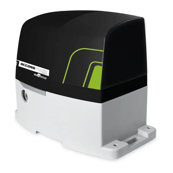
Página 5: Motorreductor Electromecánico Del Dogo1224
Figura 4 2.3.2.1 Desbloqueo del Motorreductor 1) Deslice el disco de protección 2) Inserte y gire la llave hacia de la cerradura. la derecha. 3) Tire de la manija de desbloqueo. 4) Mueva manualmente la hoja. www.accessmatic.com... -
Página 6: Fotocelda
3.1.2 Ilustración de Motores, Componentes y su Instalación El procedimiento de instalación del DOGO1224 puede modificarse debido a la gran variedad de accesorios y las cantidades a ser instaladas. No se suministra cableado de conexión de los accesorios con el KIT DOGO1224. www.accessmatic.com... -
Página 7: Conexión De La Alimentación
7) Verifique que los sensores fotográficos (opcional) están instalados en superficies niveladas para comprobar que los dos extremos de recepción y transmisión están emparejados entre sí. 8) Verifique que el área de instalación se ajusta al tamaño del sistema, y que el área sea segura y sea fácil desactivar el motorreductor. www.accessmatic.com... - Página 8 Verifique las dimensiones de los motores según las siguientes especificaciones: Figura 11 332mm 216mm 9). La instalación en el lado izquierdo y en el lado derecho, así: Puerta sin bastidor: las distancias que se indican en la Figura 12. Figura 12 50mm 50mm www.accessmatic.com...
- Página 9 Figura 14 (Apertura izquierda) 170mm 200mm Figura 15 (Apertura derecha) 170mm 200mm Figura 16 11) Si el bastidor ya está instalado en la puerta, verifique que la posición del bastidor se ajusta a los límites de tamaño indicados en la Figura 16. www.accessmatic.com...
-
Página 10: Instalación Del Motorreductor
9) Retire las dos tapas de los lados izquierdo y derecho del motorreductor como se muestra en la Figura 19. 10) Coloque el motorreductor sobre la placa y luego atornille las dos tuercas y las arandelas. Figura 20. Figura 19 Figura 20 www.accessmatic.com... - Página 11 Realice los mismos pasos para el interruptor de seguridad en la posición cerrada. Figura 23 18) Para las conexiones eléctricas de los distintos dispositivos, véase “4.1.1 Diseño de la unidad de control para el DOGO1224 . www.accessmatic.com...
-
Página 12: Instalación En Puertas Con Bastidor
(como en las partes de la Figura 28 : C & D. 11) Si es necesario, ajuste la altura del motorreductor (Max. 10mm) con las 4 espigas. Es mejor fijar el motorreductor sin el uso de espigas ya que se sujeta con firmeza y seguridad en la placa. www.accessmatic.com... - Página 13 Utilice los mismos pasos para el interruptor de seguridad instalado en la posición cerrada. 16) Para las conexiones eléctricas de los distintos dispositivos, véase “4.1.1 Diseño de la Unidad de Control para el DOGO1224 ". Figura 29 Figura 30 www.accessmatic.com...
-
Página 14: Fotocedas
RX: Conecte los terminales 1, 2 y 4 del receptor a los terminales Ph+, GND y Ph1 en el PCB. Use un cable adicional para conectar los terminales 2 y 5 en el receptor como puente. Figura 4(2) N.C. DC (12~24V) N.O. DC (12~24V) Figura 4(3) www.accessmatic.com... -
Página 15: Conexiones De La Fuente De Alimentación
4.1 Verificaciones Iniciales 4.1.1 Diseño de la unidad de control del DOGO1224 Toma de la Caja Verde Interior de la Cubierta Fotocélulas LED1 Fotocélulas LED2 aprendizaje LED3 RF Aprendizaje RF (SW1) Pantalla LED UP (SW3) SET (SW4) DOWN (SW5) 9 10 www.accessmatic.com... -
Página 16: Aprendizaje Del Transmisor
DC al activador de cierre/apertura de puerta. 2) Al utilizar baterías de reserva para suministrar la energía eléctrica, la puerta podrá abrirse y cerrarse diez veces. En la décima operación, la puerta se detendrá en el estado abierto hasta obtener un nuevo suministro eléctrico. www.accessmatic.com... -
Página 17: Ajustes De Las Funciones Programables
F7-1 1. La función puede ajustar la fuerza de funcionamiento F7-2 del motor para que sea compatible con el peso de la F7-3 puerta. F7-4 2. El ajuste de fábrica es "F7-5". F7-5 F7-6 F7-7 F7-8 F7-A F7-B F7-C www.accessmatic.com... - Página 18 Abierto FH-1 2. Stt 3 segundos FI-1 1. El ajuste de fábrica e “FI-1” 6 segundos Apertura Parcial Externa FI-2 (Modo de Cierre FI-3 9 segundos Automático por Peatón 12 segundos FI-4 Externo) 15 segundos FI-5 18 segundos FI-6 www.accessmatic.com...
-
Página 19: Funciones Programables De La Pantalla Led
LED mostrará "LEA"; y luego presione el botón del transmisor (A) una vez. Después de 1~3 segundos, la pantalla LED mostrará "ARN" "ARN": El sistema de aprendizaje está en curso. El proceso de aprendizaje automático de la puerta en movimiento: "La puerta se abre desde www.accessmatic.com... -
Página 20: Operaciones De Ajustes De Función
● Calcule la fuerza de impacto de acuerdo con la norma EN 12445. Si el control de la "fuerza motora" se utiliza para apoyar el sistema para la reducción de la fuerza del impacto, intente encontrar el ajuste que ofrece los mejores resultados. www.accessmatic.com... -
Página 21: Mantenimiento Y Eliminación
● El terminal GND de las fotocelda en la PCB debe presentar cortocircuito si no hay fotocelda instaladas. ● Verifique que el fusible funcione correctamente. El motorreductor no funciona y el relé es ● Revise si el fusible está quemado. ruidoso cuando se opera la apertura y el cierre de la puerta. www.accessmatic.com... -
Página 22: Caracterís�Cas Técnicas
Temperatura Operativa 333mm*216mm*287mm Dimensiones 10.4 kg Peso 110Vac/60Hz Fuente de alimentación principal 2 pzs de baterías para la operación de Batería de reserva emergencia, 1.2A cada una, 1.1kg 11.4A, 22V Transformador 433.92MHz; 200 memoria de transmisores Placa del receptor www.accessmatic.com... - Página 23 Opening your life MANUAL DE USUARIO SLIDING DOOR OPENER 24V DC MOTOR 1224...
- Página 24 3.3.5 PPB-1 Push Bu�on…..........15 3.4 Power Supply Connec�ons........16 4. Final Checks and Start Up 4.1 Ini�al Checks............16 4.1.1 Design of Dogo 1224 control unit....16 4.1.2 Recogni�on of LED Indica�on……......17 4.1.3 Checking the Gate Movements…….......17 4.2 Programmable Func�ons List........18 4.2.1 Programmable Func�ons of LED Display.....20...
-
Página 25: Warnings
Do not use the gate-automated system before all the procedures and instruc�ons have been carried out and Keep all the components of Dogo 1224 system and this thoroughly read. manual for further consulta�on. Test the gate-automated system weekly and have In this manual, please pay extra a�en�on to the... -
Página 26: Product Descrip�On And Applica�Ons
2.1 Applica�ons Dogo 1224 is applied for residen�al automa�on of sliding gates. Dogo 1224 has to be operated with electricity and it’s forbi- dden to be operated by back-up ba�eries for normal use. Back-up ba�eries (op�onal) are only allowed for emergent opera- �on when there is a power failure, and the gearmotor can be released by the key to move the gate manually. -
Página 27: Dogo 1224 Electromechanical Gearmotor
1224 Opening your life 2.3.1 Dogo 1224 Electromechanical Gearmotor Dogo 1224 consists of an electronic control unit and connector for the op�onal radio control recei- ver. The gearmotor could be released manually by special release keys when there is power failure. -
Página 28: Ph-2 Photocells
“pedestrian mode”. 2.3.5 PF-1 Flashing Light PF-1 flashing light is controlled by Dogo 1224 control unit and blinks when the gate is moving or blinks 3 seconds before the gate moves. The flashing light stops blinking when the gates. -
Página 29: Notes Of Motors In Opera�On
3.1 Notes of Motors in Opera�on The Dogo 1224 gate openers are applicable to per gate leaf of 600/1.200 kg in weight for residen�al use; where the perfor- mance shall be influenced by the factors such as gate dimension, weight and climate that the driven torque is necessarily to be adjusted properly. -
Página 30: Prepara�On For Motor Installa�On
Check the following items before going for installa�on: 1). Make sure the weight and dimensions of the gate conform to the opera�on range of Dogo 1224. Don’t use Dogo 1224 if the gate specifica�ons do not meet the requirements. - Página 31 Gate with rack: the distances indicated in Figure 13. Figure 13 Figure 15 (Right opening). 11) If the rack is already installed on the gate, make sure the posi�on of the rack is fi�ed for the size limits indicated in figure 16. www.accessmatic.com...
-
Página 32: Installa�On Of The Gearmotor
Opening your life 3.3.1 Installa�on of the Gearmotor The Dogo 1224 can be installed in two situa�ons: 1). Installing on gates without rack; in this condi�on must be installed first, followed by PRK-1 rack. 2). Installing on a gate with rack; in this condi�on must be connected to the exis�ng rack. - Página 33 Operate the same steps for the limit switch in the closed posi�on. 18). For electrically connec�ons of the various devices, please see “4.1.1 Design of Dogo 1224 control unit”. Operate the same steps for the limit switch in the closed posi�on.
-
Página 34: Installing On Gates With Rack
Then fix it by fastening the two nuts and washers. (as the “C” & “D” parts in Figure 28). 11). If necessary, adjust the height of the gearmotor (Max. 10mm) with the 4 dowels. It is be�er to fix the gearmotor without dowels as it is fastened firmly and securely on the plate. www.accessmatic.com... -
Página 35: Ph-2 Photocells
The brackets should be located at a sufficient distance from mechanical stops in order to keep the gate from crashing. Operate the same steps for the limit switch installed in the closed posi�on. 16). For electrically connec�ons of the various devices, please see “4.1.1 Design of Dogo 1224 Control Unit”. 3.3.2 PH-2 Photocells The safety photocells are security devices for control automa�c gates. -
Página 36: Pf-1 Flashing Light
3.) Connect the wires and penetrate the wires into the hole of the base. See Figure 3.3.3 (3). 4.) Drill the holes in the wall and fix the bo�om to the wall by three screws. See Figure 3.3.3 (4). www.accessmatic.com... -
Página 37: Pks-1 Key Selector
8). Turn the key and insert the shell on the bo�om. Turn the key back to the center posi�on and the shell will be fixed to the bo�om. 9). Tighten the lock body with the two screws and insert the round cover by pressing it to a�ach to the whole unit. www.accessmatic.com... -
Página 38: Ppb-1 Push Bu�On
3). Supply the gearmotor with the power. 4) Final Checks and Start Up 4.1 Ini�al Checks 4.1.1 Design of Dogo 1224 control unit If the Led display is in normal performing refer to “4.2.1”, you can control the gate by either transmi�ers or the bu�on on the... -
Página 39: Recogni�On Of Led Indica�On
1). Release the gearmotor with the release key and move the gate to the middle so that it is free to move in both opening and closing direc�ons; then lock the gearmotor. 2). Perform the gate opening and closing several �mes and make sure the gates reaches the limit switch at least 2~3 cen�- meters before the mechanical stop. www.accessmatic.com... - Página 40 1224 Opening your life www.accessmatic.com...
- Página 41 1224 Opening your life www.accessmatic.com...
- Página 42 1224 Opening your life www.accessmatic.com...
- Página 43 1224 Opening your life www.accessmatic.com...
- Página 44 1224 Opening your life www.accessmatic.com...
- Página 45 1224 Opening your life DG0624 DG1224 1.200 DG0624 / DG1224 www.accessmatic.com...
-
Página 46: Dogo1224
1224 Opening your life MODEL Dogo 1224 V0120 www.accessmatic.com www.accessmatic.com... - Página 47 Arandela AUACREPDG1224-030 WORM GEAR Piñón interior AUACREPDG1224-031 SPRING Resorte AUACREPDG1224-034 PACKING Empaque AUACREPDG1224-035 OIL SEAL Sello de aceite AUACREPDG1224-037 SWICH LIMIT Interruptor final de Carrera AUACREPDG1224-044 AUACREPDG1224-056- LOCK KIT Kit de chapa BRIDGE RECTIFIER Puente rectificador AUACREPDG1224-072 V0120 www.accessmatic.com www.accessmatic.com...
- Página 48 Opening your life www.accessmatic.com...