
Manuales relacionados para IB RUBINETTERIE ONLYONE OO206


Resumen de contenidos para IB RUBINETTERIE ONLYONE OO206
- Página 1 ISTRUZIONI DI MONTAGGIO FITTING INSTRUCTIONS INSTRUCTIONS DE MONTAGE INSTRUCCIONES DE MONTAJE INSTRUÇÕES DE MONTAGEM OO206 OA206...
- Página 2 Fig. Per un’installazione ottimale si consiglia di realizzare un alloggiamento con profondità compresa tra 45 mm e 60 mm fi g. 1. N.B. La misurazione dovrà tener conto della fi nitura superfi ciale (piastrelle, marmi ecc …). In ogni caso controllare che la superfi cie fi nita sia compresa tra i due livelli di massimo e minimo stampati sulla copertura in plastica fi g. 2 . For optimal installation we recommend creating a housing of between 45 mm and 60 mm deep, fi...
- Página 3 Fig. livello di massimo maximum level livello di minimo niveau maximum minimum level nivel de máximo niveau minimum nível máximo nivel de mínimo nível mínimo INGRESSO acqua calda hot water INLET ARRIVÉE eau chaud INGRESSO acqua fredda ENTRADA agua caliente cold water INLET ENTRADA água quente ARRIVÉE eau froid ENTRADA agua fría ENTRADA água fria Eseguire i collegamenti alle tubature allacciando l’acqua fredda a sinistra e l’acqua calda a destra fi g 2. Make the pipe connections by connecting the cold water to the left and the hot water to the right fi...
- Página 4 Fig. 90° COATING REVÊTEMENT RECUBRIMIENTO REVESTIMENTO Prima di fi ssare il corpo incasso verifi care la perpendicolarità rispetto alla parete ricordandosi degli ingombri di massimo e minimo forniti. Before fi xing the fl ush body ensure that it is perpendicular to the wall, remembering the maximum and minimum external dimensions supplied. Avant de fi xer le corps encastré, vérifi er la perpendicularité par rapport au mur en se souvenant des encombrements maximum et minimum fournis.
- Página 5 Fig. Fissare il corpo incasso alla parete lasciando liberi i due fori M5 del corpo incasso. Finire la parete. Togliere la protezione in plastica 4-A, svitando le due viti 4-B. Fix the fl ush body to the wall leaving the two M5 holes of the fl ush body free. Finish the wall. Remove the 4-A plastic protection, by unscrewing the two 4-B screws. Fixer le corps encastré au mur en laissant les deux trous M5 du corps encastré libres. Terminer le mur. Enlever la protection en plastique 4-A en dévissant les deux vis 4-B. Fijar el cuerpo del empotrado en la pared, dejando libres los dos orifi cios M5 del cuerpo del empotrado. Acabar la pared. Sacar la protección de plástico 4-A, desenroscando los dos tornillos 4-B. Fixar o corpo de encaixe à parede deixando livres os dois furos M5 do corpo de encaixe. Fazer o acabamento da parede. Retirar a protecção de plástico 4-A, soltando os dois parafusos 4-B.
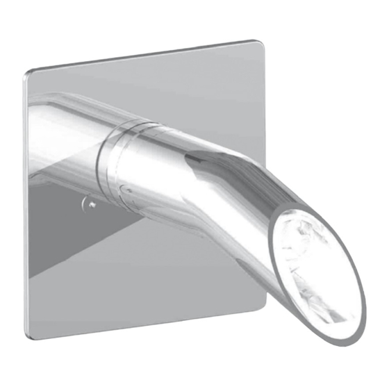
- Página 6 Fig. Innestare accuratamente la bocca 5-C sul corpo incasso fi no a fondo corsa. Fissare la bocca con il grano 5-D e coprire il foro con la placchetta 5-E. Carefully fi t the spout 5-C to the fl ush body as far as it will go. Fix the spout with the grub screw 5-D and cover the hole with the plaque 5-E. Monter soigneusement le bec 5-C sur le corps encastré jusqu’en fi n de course. Fixer le bec avec le goujon 5-D et couvrir le trou avec la petite plaque 5-E. Acoplar cuidadosamente la boquilla 5-C en el cuerpo del empotrado hasta el tope de la carrera. Fijar la boquillas con el tornillo sin cabeza 5-D y cubrir el agujero con la plaquita 5-E. Encaixar cuidadosamente a boca 5-C no corpo de encaixe até o fundo. Fixar a boca com o pino roscado 5-D e cobrir o furo com a placa 5-E.
- Página 7 Fig. Con cautela inserire la piastra 6-F e fi ssarla con le due viti 6-G. Carefully insert the plate 6-F and secure it with the two screws 6-G. Introduire soigneusement la plaque 6-F et la fi xer avec les deux vis 6-G. Introducir con cuidado la placa 6-F y fi jarla con los dos tornillos 6-G. Com cuidado, inserir a chapa 6-F e fi xá-la com os dois parafusos 6-G.
-
Página 8: Important
Rubinetterie S.p.A. IMPORTANT Via dei Pianotti 3/5 Pressure & Temperature Requirements. 25068 SAREZZO (BS) Italy • Hot and cold water inlet pressures should Iscr. Reg. Impr. BS 01785230986 be equal. R.E.A. BS 352087 • Inlet pressure range: 150-1000 kPa P.IVA IT01785230986 Capitale Sociale € 420.000,00 i.v. • New Regulation: -500 kPa maximum operating pressure at any outlet within a building. phone +39 030 802101 (Ref. AS/NZS 3500.1-2003, Clause 3.3.4) fax +39 030 803097 • Maximum hot water temperature: 80°C. mail info@ibrubinetterie.it...