Tabla de contenido
Publicidad
Idiomas disponibles
Idiomas disponibles
Instruction Sheet
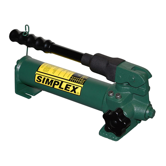
Hydraulic Hand Pumps
A Division Of Templeton, Kenly & Co., Inc.
CONTENTS
English ...................... Instruction Sheet ............................. Page ............. 2-5
Hollands .................... Handleiding ..................................... Bladzidje ....... 6-9
Français .................... Notice d'Emploi ............................... Page ......... 10-13
Deutsch ..................... Anleitungsblatt ................................ Seite ........ 14-17
Italiano ...................... Istruzioni .......................................... Pagina ...... 18-21
Español ..................... Hoja de instrucciones ..................... Página ...... 22-25
1
Publicidad
Tabla de contenido

Resumen de contenidos para Simplex P20
- Página 1 Instruction Sheet Hydraulic Hand Pumps A Division Of Templeton, Kenly & Co., Inc. CONTENTS English ...... Instruction Sheet ......Page ..... 2-5 Hollands ....Handleiding ........Bladzidje ..6-9 Français ....Notice d’Emploi ....... Page ..10-13 Deutsch ..... Anleitungsblatt ........ Seite ..14-17 Italiano ......
- Página 2 Instruction Sheet Hydraulic Hand Pumps A Division Of Templeton, Kenly & Co., Inc. ISPECIFICATIONS: Use this instruction sheet for the following hand pump models. Hand Pump Specifications Model Type Maximum Pressure Oil Volume per Stroke Usable Oil Capacity (Speed) Rating psi [bar] 2,850 [200] .16 [2.62] 20 [328]...
- Página 3 to ensure that tape does not shed into hydraulic system, causing damage. Trim loose ends. Install a pressure gauge in-line from the pump for added safety and better control. Connect the hose(s) to your cylinder or tool. OPERATION Before Using the Pump Check all system fittings and connections to be sure they are tight and leak free.
- Página 4 Position lever on 4-way valve to select function as follows: (2) Flow to port “A”; port “B” returns flow to the reservoir (3) Neutral; ports “A” and “B” are blocked (4) Flow to port “B”; port “A” returns flow to the reservoir Operate pump to perform work.
-
Página 5: Troubleshooting Guide
NOTE: Non-vented hand pumps require air in the reservoir to function properly. If the reservoir is completely filled, a vacuum will form preventing oil from flowing out of the pump. Keep Oil Lines Clean When coupler halves are disconnected, always screw on dust caps. Use every precaution to guard unit against entrance of dirt because foreign matter may cause pump, cylinder, or valve failure. - Página 6 P41, P42, P20, P22 Figuur 1 en de corresponderende tabel onderaan tonen de belangrijkste onderdelen van de handpompmodellen P41, P42, P20 en P22. De uitlaat/vuldop (dubbel gebruik) doet dienst als drukontlastklep in geval van toevallige drukverhoging in het reservoir. Om een inlaatopening aan de achterkant van het reservoir aan te brengen voor kleppen op afstand, gebruik een terug-naar-het- reservoir-kit.
-
Página 7: Installatie
INSTALLATIE Het aansluiten van de pomp Pas de slang in de pompopening. Gebruik anderhalve wikkeling teflontape (of gepast afsluitproduct) op de slangfitting. Breng geen tape aan op het eerste stuk draad om te verzekeren dat de tape niets lost in het hydraulisch systeem en daar schade veroorzaakt. - Página 8 Figuur 2 Dubbelwerkende toepassingen manuele met vierweg/driestand klep Pompen met vierwegcontrolekleppen werden ontworpen om dubbelwerkende cylinders te bewerken. Stel hendel op vierwegklep af om een functie te kiezen als volgt: (2) Vloeit naar opening “A”; opening “B” stuwt door naar het reservoir (3) Neutraal;...
-
Página 9: Problemen Oplossen
ONDERHOUD Voeg olie toe aan pomp. Kijk het olieniveau regelmatig na. WAARSCHUWING Voeg olie enkel toe wanneer de cylinders ingetrokken (uitgetrokken bij trekcylinders) zijn. Anders zal het toestel meer olie bevatten dan het reservoir kan bevatten. Verwijder de uitlaat/vuldop van het reservoir. Vul het reservoir enkel totaan het merkteken. - Página 10 Fiche d’instruction Pompes à main hydrauliques A Division Of Templeton, Kenly & Co., Inc. CARACTÉRISTIQUES Utiliser cette fiche d’instruction pour les modèles de pompe à main ci-dessous. Caractéristiques de pompe à main Modèle Type Pression nominale Volume d’huile par Capacité d’huile (vitesse) max.
- Página 11 INSTALLATION Branchement de la pompe Visser le flexible sur la sortie de la pompe. Appliquer 1 tour de ruban téflon (ou matériau d’étanchéité adéquat) sur le raccord du flexible en veillant à ne pas couvrir le premier filet afin que des fragments de ruban ne risquent pas de pénétrer dans le circuit, causant des dommages.
- Página 12 Figure 2 Applications à double effet avec distributeur manuel à 4 voies, 3 positions Les pompes à distributeur à 4 voies sont conçues pour actionner les vérins à double effet. Voir les positions du distributeur. La manette du distributeur à 4 voies permet de sélectionner les fonctions comme suit : (1) Écoulement vers l’orifice “A”;...
-
Página 13: Guide De Dépannage
Appoint d’huile de la pompe Vérifier le niveau d’huile régulièrement. AVERTISSEMENT Toujours faire l’appoint d’huile avec les vérins complètement rétractés (étendus dans le cas de vérins de traction), sans quoi le circuit contiendra une quantité d’huile supérieure à la capacité du réservoir. Retirer le bouchon de remplissage/reniflard du réservoir. - Página 14 Anleitungsblatt Hydraulische Handpumpen A Division Of Templeton, Kenly & Co., Inc. TECHNISCHE DATEN Dieses Anleitungsblatt gilt für die folgenden Handpumpenmodelle: Technische Daten, Handpumpen Modell Typ Max. Druck Ölmenge pro Hub Nutzbare Ölkapazität (Geschw.-Stufen) Nennwert psi [bar] 2,850 [200] .16 [2.62] 20 [328] 10,000 [700] .16 [2.62]...
- Página 15 freilassen, um sicherzustellen, daß keine Bandfetzen in das Hydrauliksystem gelangen und Schaden verursachen. Die losen Enden abschneiden. Zur erhöhten Sicherheit und besseren Kontrolle einen Druckmesser in der von der Pumpe kommenden Leitung installieren. Den Schlauch bzw. die Schläuche an den Zylinder oder das Werkzeug anschließen.
- Página 16 Abbildung 2 Doppeltwirkende Anwendungen mit manuellem Vierwegeventil, 3 Positionen Pumpen mit Vierwege-Steuerventilen sind für den Betrieb von doppeltwirkenden Zylindern vorgesehen. Die Ventilpositionen sind in Abbildung. Den Hebel am Vierwegeventil zur Funktionsauswahl wie folgt einstellen: (1) Fluß zu Anschluß “A”; Flußrücklauf zum Behälter über Anschluß “B” (2) Neutral;...
- Página 17 Die obigen Schritte nach Bedarf wiederholen. Nachfüllen von Öl in der Pumpe Ölstand regelmäßig prüfen. VORSICHT Öl nur nachfüllen, wenn die Zylinder vollständig eingefahren sind (bzw. ausgefahren, wenn Zugzylinder verwendet werden), da das System andernfalls mehr Öl enthält als der Behälter aufnehmen kann. Entlüftungs-/Füllkappe vom Behälter entfernen.
- Página 18 Istruzioni Pompe oleodinamiche manuali A Division Of Templeton, Kenly & Co., Inc. DATI TECNICI Seguire le istruzioni qui presentate per i seguenti modelli di pompe manuali. Dati tecnici delle pompe manuali Modello Tipo Pressione massima Volume d’olio per Volume d’olio utilizzabile (regime) nominale (psi [bar]) corsa (in...
- Página 19 (o usando un sigillante per filetti adatto) per un giro e mezzo sul raccordo del tubo, lasciando l’intero primo filetto senza nastro, affinché da quest’ultimo non si stacchino pezzi che penetrando nel sistema oleodinamico potrebbero causare danni. Tagliare le estremità volanti del nastro. Installare un manometro in linea a valle della pompa, per ulteriore sicurezza e una regolazione migliore.
- Página 20 Figura 2 Sistemi a doppio effetto con valvola manuale a 4 vie e 3 posizioni Le pompe munite di regolatori di portata a 4 vie servono ad azionare cilindri a doppio effetto. Portare la leva di una valvola a 4 vie nella posizione adatta come segue: Flusso verso la bocca “A”;...
-
Página 21: Ricerca Guasti
Rabbocco dell’olio della pompa Controllare regolarmente il livello dell’olio. AVVISO Rabboccare sempre l’olio con i cilindri completamente retratti (estesi se sono da tiro), altrimenti il sistema si riempie di più olio di quanto non ne possa essere contenuto nel serbatoio. Togliere dal serbatoio il tappo di rabbocco/sfiato. -
Página 22: Especificaciones De La Bomba Manual
Hoja de instrucciones Bombas hidráulicas manuales A Division Of Templeton, Kenly & Co., Inc. ESPECIFICACIONES Usar esta hoja de instrucciones para los modelos de bombas manuales siguientes. Especificaciones de la bomba manual Modelo Tipo Presión nominal Volumen de aceite Capacidad utilizable (cm (Velocidad) máxima psi[bar] por carrera pulg... -
Página 23: Operacion
sellante para roscas adecuado), dejando el primer hilo de rosca completo sin cinta para asegurar que ésta no se deshilacha al interior del sistema y lo dañe. Recortar los extremos sueltos. Para mayor seguridad y mejor control, instalar una manómetro en línea desde la bomba. - Página 24 Las bombas con válvulas de control de 4 vías están diseñadas para accionar cilindros de doble efecto. Para las posiciones de la válvula. Colocar la palanca en la válvula de 4 vías para escoger la función de la manera siguiente: (1) Flujo a la lumbrera “A”;...
-
Página 25: Guia De Localizacion De Averias
Quitar la tapa de ventilación/llenado del depósito. Llenar el depósito solamente hasta la marca de nivel que se muestra en la bomba. Si es necesario, purgar el aire del sistema. Volver a revisar el nivel de aceite después de purgar el aire. Volver a colocar la tapa de ventilación/llenado en su lugar.