Tabla de contenido
Publicidad
Idiomas disponibles
Idiomas disponibles
OPERATION - INSTALLATION - SERVICE MANUAL
Unità terminali canalizzabili
IT
idronici a comando elettronico
ed elettromeccanico.
Ductable hydronic terminal
EN
u n i t s w i t h e l e c t r o n i c a n d
electromechanical control.
Unités terminales hydrauliques
FR
gainables à commande électronique
et électromécanique
DE
Elektronisch/elektromechanisch
gesteuerte Kühler-Ventilator-
Einheiten für Kanalanschluß.
ES Unidades terminales de conductos
hidrónicos con mando electrónico
y electromecánico.
HWD
602÷1104
Publicidad
Capítulos
Tabla de contenido

Resumen de contenidos para CLIMAVENETA HWD 602
- Página 1 OPERATION - INSTALLATION - SERVICE MANUAL Unità terminali canalizzabili idronici a comando elettronico ed elettromeccanico. Ductable hydronic terminal u n i t s w i t h e l e c t r o n i c a n d electromechanical control.
- Página 3 INDICE Avvertenze generali Resa termica batteria aggiuntiva Regole fondamentali di sicurezza Perdite di carico accessori Identificazione Modalità di funzionamento HWD Ricevimento prodotto e movimentazione Controllo e avviamento unità Descrizione unità standard Modalità di taratura del ventilatore HWD Disegni dimensionali Manutenzione ordinaria Installazione Manutenzione Stagionale Spazi funzionali...
-
Página 4: Avvertenze Generali
AVVERTENZE GENERALI Le unità terminali HWD sono l’unità interna di La documentazione fornita con l’unità deve un sistema idronico canalizzato. Abbinate a refrigera- essere consegnata al proprietario affinché la conser- tori d’acqua costituiscono un sistema per il solo raf- vi con cura per eventuali future consultazioni. freddamento, abbinate a refrigeratori d’acqua reversi- Al momento della consegna della merce da bili a pompa di calore costituiscono un sistema per il... - Página 5 IDENTIFICAZIONE I terminali idronici HWD sono identificabili attraverso: Etichetta imballo De' Longhi S.p.a. - 31100 Treviso / Italia Via L.Seitz, 47 - tel. 04224131 fax 0422413659 Riporta i dati identificativi del prodotto. MODELLO: TENSIONE: CODICE: Targhetta tecnica Riporta i dati tecnici e prestazionali dell’apparecchio. In caso di smarrimento richiedere un duplicato al Servizio post vendita.
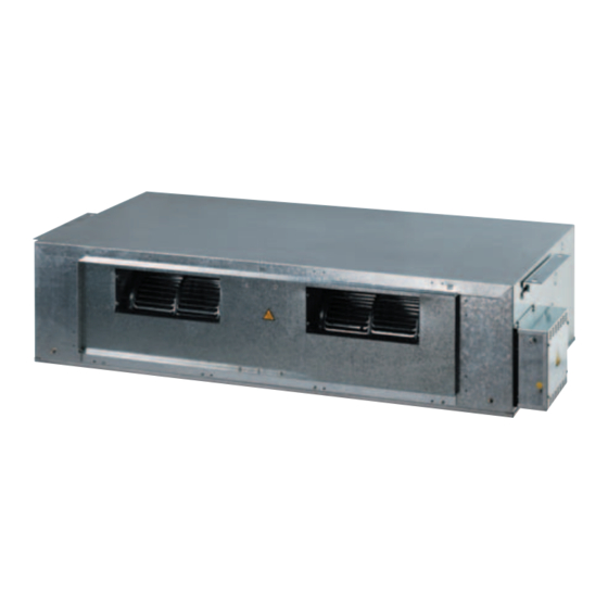
- Página 6 DESCRIZIONE UNITÁ STANDARD Le unità HWD sono destinate ad istallazione da incas- ACCESSORI so. Abbinate ai numerosi accessori disponibili consentono la rea- - Plenum di aspirazione a due vie con serranda. lizzazione di impianti per la distribuzione dell’aria ed un controllo - Modulo batteria di riscaldamento ad acqua calda.
-
Página 7: Disegni Dimensionali
DISEGNI DIMENSIONALI attacco acqua in attacco acqua out filtro aria copertura ventilatore copertura vano batteria accesso filtro aria accesso scarico condensa quadro elettrico 48.5 Grandezza Dimensioni (mm) 602 - 703 803 - 904 1050 1100 1003 - 1104 1250 1300 Grandezza Attacchi Peso... -
Página 8: Collegamenti Idraulici
SPAZI FUNZIONALI (*) Min. 100 mm Min. 400 mm Nota: mantenere una inclinazione minima di 2 mm/m verso lo scarico condensa ( * ) Min. 400 mm solo nel caso di montaggio Modulo Purificatore d’aria COLLEGAMENTI IDRAULICI COLLEGAMENTO TUBAZIONE ACQUA 4. -
Página 9: Circuito Idraulico
CIRCUITO IDRAULICO Per un corretto funzionamento dell’unità è necessario po- sizionare la sonda ambiente BT1 in modo tale da esser investita direttamente dal flusso d’aria di aspirazione (lunghezza cavo sonda BT1 3 m). Avvertenze: se presente il modulo umidificatore effettuare SERBATOIO il collegamento dello scarico troppo pieno e dello scarico ACQUA... -
Página 10: Collegamenti Elettrici Di Potenza
COLLEGAMENTI ELETTRICI DI POTENZA COLLEGAMENTI AUSILIARI Per il collegamento funzionale dell’unità portare il cavo di ali- Tutti i morsetti cui si farà riferimento nelle prossime spie- mentazione del quadro elettrico all’interno dell’unità e colle- gazioni fanno parte della morsettiera situata sulla scheda garsi ai morsetti (L) fase, (N) neutro e (PE) terra, elettronica. -
Página 11: Schemi Elettrici
SCHEMI ELETTRICI Italiano 07/13... - Página 12 Schema collegamenti elettrici unità standard HWD con valvola per batteria principale HWD ELECTRICAL BOARD I S1 I S 3 I S 4 PTH2 Schema collegamenti elettrici unità standard HWD con batteria ad acqua aggiuntiva, valvole ed umidificatore HWD E L EC TR ICAL B OARD HOT WATER PURIFIER HUMIDIFIE R...
- Página 13 Schema collegamenti elettrici unità standard HWD con resistenza elettrica generale, umidificatore e valvole sulla batteria principale HUMIDIFIER HWD ELECTRICAL BOARD HEATER PURIFIER ELECTRICAL BOARD MAX LOAD FOR EXIT N° 5=3A-230V I S4 PTH2 Schema collegamenti elettrici unità standard HWD con resistenza elettrica di serie, umidificatore e valvole sulla batteria principale HUMIDIFIER HEATER HWD ELECTRICAL BOARD...
-
Página 14: Dati Tecnici Generali
DATI TECNICI GENERALI Grandezza 1003 1104 Potenzialità frigorifera totale (1) 10,2 12,1 15,8 Potenzialità frigorifera sensibile (1) 10,7 Potenzialità termica (2) 11,3 14,5 Potenza termica batteria aggiuntiva (3) 11,8 11,8 16,7 18,0 Perdite di carico batteria standard (1) Perdite di carico batteria aggiuntiva (3) Potenza assorbita max 0,37 0,37... - Página 15 CURVE PRESTAZIONALI VENTILATORI CURVE PRESTAZIONALI HWD 602 1000 1100 1200 1300 1400 1500 1600 1700 1800 1900 2000 2100 CURVE PRESTAZIONALI HWD 703 1000 1100 1200 1300 1400 1500 1600 1700 1800 1900 2000 2100 CURVE PRESTAZIONALI HWD 803 1000...
- Página 16 CURVE PRESTAZIONALI HWD 904 1000 1100 1200 1300 1400 1500 1600 1700 1800 1900 2000 2100 CURVE PRESTAZIONALI HWD 1003 1000 1200 1400 1600 1800 2000 2200 2400 2600 2800 3000 3200 3400 CURVE PRESTAZIONALI HWD 1104 1000 1200 1400 1600 1800 2000...
- Página 17 PRESTAZIONI IN RAFFREDDAMENTO Velocità massima Italiano 07/13...
- Página 18 Velocità massima Italiano 07/13...
- Página 19 Velocità massima Italiano 07/13...
-
Página 20: Velocità Massima
PRESTAZIONI IN RISCALDAMENTO Velocità massima Grandezza 602 Tai 0°C Tai 10°C Tai 15°C Tai 18°C Tai 20°C Tai 22°C [˚C] [l/h] [kPa] [kW] [˚C] [kW] [˚C] [kW] [˚C] [kW] [˚C] [kW] [˚C] [kW] [˚C] 17,0 22,8 25,7 27,4 28,5 29,7 16,0 19,8 24,9... - Página 21 Grandezza 904 Tai 0°C Tai 10°C Tai 15°C Tai 18°C Tai 20°C Tai 22°C [˚C] [l/h] [kPa] [kW] [˚C] [kW] [˚C] [kW] [˚C] [kW] [˚C] [kW] [˚C] [kW] [˚C] 1.000 13,2 24,5 10,0 28,4 30,4 31,6 32,3 33,1 1.760 21,0 14,8 27,5 11,1...
- Página 22 ACCESSORI DISPOSIZIONE ACCESSORI 1 unità canalizzabile 4 batteria aggiuntiva ad acqua per riscaldamento modulo umidificatore 9 modulo purificazione aria 2 plenum aspirazione a due vie con serranda invernale (montata all’interno dell’unità) plenum di mandata 10 filtro carboni attivi 3 plenum di aspirazione 5 modulo resistenza elettrica plenum di mandata per condotti cirarilari Grandezza...
- Página 23 BATTERIA AD ACQUA AGGIUNTIVA La batteria ad acqua per il riscaldamento invernale viene impie- zione di tipo on/off per HWD. Il controllo della valvola è gesti- gata in abbinamento ad una caldaia. Il montaggio della batteria è to direttamente dal termostato ambiente PTH2 per HWD. La previsto per attacchi destri.
- Página 24 PLENUM DI MANDATA (E ASPIRAZIONE) Il plenum di mandata e aspirazione è fornito qualora sia ne- altri accessori ed è dotato di pareti pretranciate che ne cessario aspirare o mandare il flusso d’aria da/o in basso. consentono un utilizzo ottimale e flessibile. È...
- Página 25 PLENUM DI MANDATA A CONDOTTI CIRCOLARI Il plenum di mandata per condotti circolari consente la di- Il numero dei canali è stato dimensionato al fine di ottene- stribuzione dell’aria attraverso tubazioni flessibili. La distri- re velocità d’aria nei condotti pari a 5,0 m/s con portata buzione avviene su 4 canali Ø160 mm per unità...
- Página 26 RESA TERMICA BATTERIA AGGIUNTIVA Grandezza 602-703 Tai: -5°C Tai: 0°C Tai:10°C Tai:15°C Tai: 20°C Tai: 22°C ∅ Pw °C °C °C °C °C °C °C 17,2 20,1 27,7 31,6 34,8 36,1 18,0 21,3 28,4 31,7 35,3 36,6 10,0 18,9 22,5 29,1 32,7 36,0...
- Página 27 PERDITE DI CARICO ACCESSORI PERDITE DI CARICO LATO ARIA BATTERIA AGGIUNTIVA Grandezza Qaria m 1100 1200 1300 1400 1500 1600 ∅ pa 602-703 (Pa) Grandezza Qaria m 1200 1300 1400 1500 1600 1700 ∅ pa 803-904 (Pa) Grandezza Qaria m 1800 1900 2000...
-
Página 28: Controlli Preliminari
MODALITÁ DI FUNZIONAMENTO HWD L’unità terminale HWD per il suo corretto funzionamento Una volta selezionata la modalità di funzionamento (estivo deve essere abbinata ad un termostato ambiente con esta- o invernale). te/inverno e ad un commutatore di velocità posto nell’am- Il funzionamento dell’unità... - Página 29 MODALITÁ DI TARATURA DEL VENTILATORE HWD Ogni modello di macchina viene fornito con le caratteristi- A) e la velocità max disponibile (curva D) è stato suddiviso che di prestazione del ventilatore, velocità massima, media in sette parti corrispondenti alle curve indicate nei rispetti- e minima come indicato nei rispettivi diagrammi di ogni vi diagrammi delle unità.
-
Página 30: Manutenzione Ordinaria
MANUTENZIONE ORDINARIA IMPORTANTE: CONTROLLO STATO PULIZIA DEI FILTRI ARIA - Eseguire tutte le operazioni di manutenzione o pulizia A seconda dell’ambiente in cui è installata l’unità interna, oc- con l’unità non in tensione. corre periodicamente pulire i filtri aria. In ambienti particolar- - È... -
Página 31: Informazioni Utili
Per informazioni relative all’assistenza tecnica e al reperimento delle parti di ricambio potete contattare: CLIMAVENETA S.P.A. UFFICIO POST VENDITA - SETTORE RESIDENZIALE Via Duca d’Aosta 121 - 31031 Mignagola di Carbonera (TV) ITALIA www.climaveneta.it – info@climaveneta.it Numero Verde 800 019 190 Italiano 07/13... - Página 33 INDEX General warnings Heat output of auxiliary hot water coil Fundamental safety rules Pressure drop with accessories Identification Operating modes HWD Receiving and handling the product Checking and starting up the unit Description of standard unit Fan calibration mode HWD Dimensional drawings Routine maintenance Installation...
-
Página 34: General Warnings
GENERAL WARNINGS HWD terminal units are the internal units of a The documentation supplied with the unit ductable hydronic system. When used in combination must be consigned to the owner who should keep it with water chillers, they form a cooling only system, carefully for future consultation. -
Página 35: Packaging Label
IDENTIFICATION HWD hydronic terminals can be identified by the: Packaging label De' Longhi S.p.a. - 31100 Treviso / Italia Via L.Seitz, 47 - tel. 04224131 fax 0422413659 Giving the data identifying the product. MODEL: VOLTAGE: CODE: Rating plate Giving the technical and performance data of the unit. If this is lost, ask the After Sales Service for a replacement. -
Página 36: Heat Exchange Coil
DESCRIPTION OF STANDARD UNIT HWD units are designed for flush mounting. In combination ACCESSORIES with the numerous accessories available, they can be used to - Two-way intake plenum with damper create high specification installations for air distribution and - Activated carbon filter environmental temperature and humidity control. -
Página 37: Dimensional Drawings
DIMENSIONAL DRAWINGS water in connection water out connection air filter fan cover coil compartment cover air filter access condensate drain access electrical switchboard 48.5 Size Dimensions (mm) 602 - 703 803 - 904 1050 1100 1003 - 1104 1250 1300 Size Connections Weight... -
Página 38: Hydraulic Connections
MINIMUM INSTALLATION DISTANCES (*) Min. 100 mm Min. 400 mm Note: the unit must slope by at least 2 mm/m towards the condensate drain. ( * ) Min. 400mm only in if the Air purifier Module is fitted. HYDRAULIC CONNECTIONS WATER PIPE CONNECTION 4. -
Página 39: Power Connections
HYDRAULIC CIRCUIT For correct operation of the unit, the BT1 room sensor must be positioned directly in the inflow of air (BT1 sen- sor cable length: 3m). Warnings: if the humidifier module is present, the overflow pipe and seasonal drain valve should be connected, as de- WATER TANK scribed in the paragraph “connecting the condensate drain pipe”. -
Página 40: Auxiliary Connections
HYDRAULIC CONNECTIONS AUXILIARY CONNECTIONS To connect the unit, bring the power cable to the electrical All the terminals referred to in the following explanations switchboard inside the unit and connect it to the phase (L), are to be found on the terminal board located on the elec- neutral (N) and earth (PE) terminals, including a suitable tronic board. -
Página 41: Electrical Wiring Diagrams
ELECTRICAL WIRING DIAGRAMS English 07/13... - Página 42 Electrical connection diagram, standard HWD unit with valve for main coil HWD ELECTRICAL BOARD I S1 I S 3 I S 4 PTH2 Electrical connection diagram, standard HWD unit with auxiliary water coil, valves and humidifier HWD E L EC TR ICAL B OARD HOT WATER PURIFIER HUMIDIFIE R...
- Página 43 Electrical connection diagram, standard HWD unit with general electric heater, humidifier and valves on the main coil HUMIDIFIER HWD ELECTRICAL BOARD HEATER PURIFIER ELECTRICAL BOARD MAX LOAD FOR EXIT N° 5=3A-230V I S4 PTH2 Electrical connection diagram, standard HWD unit with electric heater as standard, humidifier and valves on the main coil HUMIDIFIER HEATER HWD ELECTRICAL BOARD...
-
Página 44: General Technical Data
GENERAL TECHNICAL DATA Size 1003 1104 Total cooling capacity (1) 10,2 12,1 15,8 Sensible cooling capacity (1) 10,7 Heat output (2) 11,3 14,5 Heating capacity supplementary coil (3) 11,8 11,8 16,7 18,0 Pressure drop standard coil (1) Pressure drop auxiliary coil (3) Max absorbed power 0,37 0,37... - Página 45 FAN PERFORMANCE CURVES PERFORMANCE CURVES HWD 602 1000 1100 1200 1300 1400 1500 1600 1700 1800 1900 2000 2100 PERFORMANCE CURVES HWD 703 1000 1100 1200 1300 1400 1500 1600 1700 1800 1900 2000 2100 PERFORMANCE CURVES HWD 803 1000...
- Página 46 PERFORMANCE CURVES HWD 904 1000 1100 1200 1300 1400 1500 1600 1700 1800 1900 2000 2100 PERFORMANCE CURVES HWD 1003 1000 1200 1400 1600 1800 2000 2200 2400 2600 2800 3000 3200 3400 PERFORMANCE CURVES HWD 1104 1000 1200 1400 1600 1800 2000...
- Página 47 COOLING PERFORMANCE Maximum speed English 07/13...
- Página 48 Maximum speed English 07/13...
- Página 49 Maximum speed English 07/13...
- Página 50 HEATING PERFORMANCE Maximum speed Size 602 Tai 0°C Tai 10°C Tai 15°C Tai 18°C Tai 20°C Tai 22°C [˚C] [l/h] [kPa] [kW] [˚C] [kW] [˚C] [kW] [˚C] [kW] [˚C] [kW] [˚C] [kW] [˚C] 17,0 22,8 25,7 27,4 28,5 29,7 16,0 19,8 24,9 27,4...
- Página 51 Size 904 Tai 0°C Tai 10°C Tai 15°C Tai 18°C Tai 20°C Tai 22°C [˚C] [l/h] [kPa] [kW] [˚C] [kW] [˚C] [kW] [˚C] [kW] [˚C] [kW] [˚C] [kW] [˚C] 1.000 13,2 24,5 10,0 28,4 30,4 31,6 32,3 33,1 1.760 21,0 14,8 27,5 11,1...
-
Página 52: Installing Accessories
ACCESSORIES LAYOUT OF ACCESSORIES 1 ductable unit 3 intake plenum 6 humidifier module 9 air purification module 2 two way intake plenum with winter 4 auxiliary water coil for heating 7 discharge plenum 10 activated carbon filter damper (fitted inside unit) 5 electric heater module 8 discharge plenum for round ducting Size... - Página 53 AUXILIARY WATER COIL The water coil module for winter heating is used in combina- The valve is controlled directly directly by the PTH2 room tion with a boiler. The module can be mounted using either thermostat for the HWD. right hand or left hand connections. The coil is fitted with The BT3 sensor supplied as standard in the module acts as special valves for venting the air or draining the water in the a minimum thermostat.
- Página 54 DISCHARGE (AND INTAKE) PLENUM The discharge and intake plenum is supplied when the in- It has a flange for connection to the basic unit or other ac- coming or outgoing air flow must be directed to or from cessories and blanked panels for optimum and flexible use. the bottom of the unit.
- Página 55 DISCHARGE PLENUM FOR ROUND DUCTING The discharge plenum for round ducting enables the air to be The number of ducts is calculated so as to obtain an air speed distributed through flexible ducts. Distribution takes place of 5.0 m/s in the ducts with rated air flow and the ducts fully through four 160 mm diam.
- Página 56 HEAT OUTPUT OF AUXILIARY COIL Size 602-703 Tai: -5°C Tai: 0°C Tai:10°C Tai:15°C Tai: 20°C Tai: 22°C ∅ Pw °C °C °C °C °C °C °C 17,2 20,1 27,7 31,6 34,8 36,1 18,0 21,3 28,4 31,7 35,3 36,6 10,0 18,9 22,5 29,1 32,7...
- Página 57 PRESSURE DROP ACCESSORIES PRESSURE DROP AIR SIDE AUXILIARY COIL Size Q air m 1100 1200 1300 1400 1500 1600 ∅ pa 602-703 (Pa) Size Q air m 1200 1300 1400 1500 1600 1700 ∅ pa 803-904 (Pa) Size Q air m 1800 1900 2000...
- Página 58 OPERATING MODES HWD To operate correctly, the HWD terminal must be com- Once summer or winter mode has been selected, bined with a room thermostat with summer/winter and fan operation of the unit at the speed selected is controlled speed selector functions located in the room being air con- exclusively by the room thermostat.
- Página 59 FAN CALIBRATION MODE HWD Each model of unit is supplied with the fan performance speed set (curve A) and the maximum speed available characteristics, maximum, medium and minimum speed as (curve D) has been divided into seven equal parts as repre- shown in the respective diagrams of each unit for the sented in the respective diagrams.
-
Página 60: Routine Maintenance
ROUTINE MAINTENANCE IMPORTANT: CHECKING THE STATE OF AIR FILTERS - Power to the unit must be disconnected before carrying Depending on the environment where the internal unit is installed, the out maintenance or cleaning. air filters need cleaning periodically. In particularly dusty atmospheres, - At the beginning of the season you are recommended to the air filters should be cleaned every three months and you are recom- contact qualified personnel for the seasonal start-up. -
Página 61: Seasonal Maintenance
SEASONAL MAINTENANCE These operations should be carried out by qualified per- 4. If the humidifier module is present, turn off the power sonnel only. supply. Empty the water pan by means of the cock pro- 1. Check correct operation of accessories. vided. -
Página 63: Tabla De Contenido
TABLE DES MATIÈRES Généralités Rendement thermique batterie supplémentaire 24 Consignes générales de sécurité Pertes de charge des accessoires Identification Mode de fonctionnement carte de contrôle HWD Réception du produit et manutention Contrôle et démarrage de l'unité Description unité standard Mode de réglage du ventilateur HWD Dimensions Entretien ordinaire Installation... -
Página 64: U I A
GÉNÉRALITÉS Les unités HWD sont des unités terminales inté- La documentation fournie doit être remise au rieures d'un système hydraulique. Elles sont utilisées propriétaire afin qu'il la conserve avec soin pour soit en climatisation seule associées à un groupe pouvoir la consulter le cas échéant. d’eau glacée ou en climatisation et chauffage asso- Au moment de la livraison de la marchandise ciées à... -
Página 65: U I A
IDENTIFICATION Les unités terminales hydrauliques HWD sont identi- fiables à travers: De' Longhi S.p.a. - 31100 Treviso / Italia Via L.Seitz, 47 - tel. 04224131 fax 0422413659 L'étiquette d'emballage MODÈLE: TENSION: CODE: Porte les données identifiant le produit. Plaquette technique Indique les caractéristiques techniques et les performances de l'appareil. -
Página 66: Description Unité Standard
DESCRIPTION UNITÉ STANDARD Les unités HWD sont conçues pour être posées de réglage et borniers pour le branchement à l'alimentation dans un faux-plafond. Associées aux nombreux acces- électrique, aux commandes auxiliaires et au thermostat soires disponibles elles permettent de réaliser des installa- d'ambiance PTH2 (seulement HWD). -
Página 67: Dimensions
DIMENSIONS raccord eau entrée raccord eau sortie filtre air carter ventilateurs carter logement batterie accès filtre à air accès évacuation des condensats tableau électrique 48.5 Modèle Dimensions (mm) 602 - 703 803 - 904 1050 1100 1003 - 1104 1250 1300 Modèle Raccords... -
Página 68: Espaces Fonctionnels
ESPACES FONCTIONNELS (*) Min. 100 mm Min. 400 mm Note: maintenir une inclinaison minimum de 2 mm/m vers l'évacuation des condensats. ( * ) Min. 400 mm seulement en cas de montage du Module Purificateur d'air. RACCORDEMENTS HYDRAULIQUES RACCORDEMENT TUYAUTERIE EAU 4. -
Página 69: Circuit Hydraulique
CIRCUIT HYDRAULIQUE Pour un bon fonctionnement de l'unité il est nécessaire de placer la sonde d'ambiance BT1 de façon à ce qu'elle soit directement influencée par le flux d'air d'aspiration (longueur du câble de la sonde BT1 3 m). RÉSERVOIR� D'EAU Attention: si le module humidificateur est présent effec- tuer le raccordement du trop plein et de la vanne de purge... - Página 70 RACCORDEMENTS ÉLECTRIQUES RACCORDEMENTS AUXILIAIRES Pour le raccordement fonctionnel de l'unité amener le câble Toutes les bornes indiquées dans les explications suivantes d'alimentation du tableau électrique à l'intérieur de l'unité et font partie du bornier situé sur la carte électronique. le connecter aux bornes (L) phase, (N) neutre et (PE) terre, en interposant entre la ligne et l'unité...
-
Página 71: Schémas Électriques
SCHÉMAS ÉLECTRIQUES Français 07/13... - Página 72 Schéma raccordements électriques unité standard HWD avec vanne pour batterie principale HWD ELECTRICAL BOARD I S1 I S 3 I S 4 PTH2 Schéma raccordements électriques unité standard HWD avec batterie à eau supplémentaire, vannes et humidificateur HWD E L EC TR ICAL B OARD HOT WATER PURIFIER HUMIDIFIE R...
- Página 73 Schéma raccordements électriques unité standard HWD avec résistance électrique générale, humidificateur et vannes sur la batterie principale HUMIDIFIER HWD ELECTRICAL BOARD HEATER PURIFIER ELECTRICAL BOARD MAX LOAD FOR EXIT N° 5=3A-230V I S4 PTH2 Schéma raccordements électriques unité standard HWD avec résistance électrique de série, humidificateur et vannes sur la batterie principale HUMIDIFIER HEATER HWD ELECTRICAL BOARD...
-
Página 74: Caractéristiques Techniques Générales
CARACTÉRISTIQUES TECHNIQUES GÉNÉRALES Modèle 1003 1104 Puissance frigorifique totale (1) 10,2 12,1 15,8 Puissance frigorifique sensible (1) 10,7 Puissance thermique (2) 11,3 14,5 Puissance thermique batterie supplémentaire (3) 11,8 11,8 16,7 18,0 Pertes de charge batterie standard (1) Pertes de charge batterie supplémentaire (3) Puissance absorbée 0,37 0,37... -
Página 75: Courbes Des Performances Des Ventilateurs
COURBES DES PERFORMANCES DES VENTILATEURS COURBES DES PERFORMANCES HWD 602 1000 1100 1200 1300 1400 1500 1600 1700 1800 1900 2000 2100 COURBES DES PERFORMANCES HWD 703 1000 1100 1200 1300 1400 1500 1600 1700 1800 1900 2000 2100 COURBES DES PERFORMANCES HWD 803... - Página 76 COURBES DES PERFORMANCES HWD 904 1000 1100 1200 1300 1400 1500 1600 1700 1800 1900 2000 2100 COURBES DES PERFORMANCES HWD 1003 1000 1200 1400 1600 1800 2000 2200 2400 2600 2800 3000 3200 3400 COURBES DES PERFORMANCES HWD 1104 1000 1200 1400...
-
Página 77: Performances En Refroidissement
PERFORMANCES EN REFROIDISSEMENT Vitesse maximum Français 07/13... - Página 78 Vitesse maximum Français 07/13...
- Página 79 Vitesse maximum Français 07/13...
-
Página 80: Performances En Chauffage
PERFORMANCES EN CHAUFFAGE Vitesse maximum Modèle 602 Tai 0°C Tai 10°C Tai 15°C Tai 18°C Tai 20°C Tai 22°C [˚C] [l/h] [kPa] [kW] [˚C] [kW] [˚C] [kW] [˚C] [kW] [˚C] [kW] [˚C] [kW] [˚C] 17,0 22,8 25,7 27,4 28,5 29,7 16,0 19,8 24,9... - Página 81 Modèle 904 Tai 0°C Tai 10°C Tai 15°C Tai 18°C Tai 20°C Tai 22°C [˚C] [l/h] [kPa] [kW] [˚C] [kW] [˚C] [kW] [˚C] [kW] [˚C] [kW] [˚C] [kW] [˚C] 1.000 13,2 24,5 10,0 28,4 30,4 31,6 32,3 33,1 1.760 21,0 14,8 27,5 11,1...
-
Página 82: Accessoires
ACCESSOIRES DISPOSITION ACCESSOIRES 1 unité gainable 3 plénum aspiration 5 module résistance électrique 8 plénum de refoulement pour conduits circulaires 2 plénum aspiration à deux voies avec 4 batterie supplémentaire à eau pour 6 module humidificateur 9 module purification air registre (sur une voie) chauffage (montée à... - Página 83 BATTERIE A EAU SUPPLÉMENTAIRE La batterie à eau pour le chauffage en hiver est employée en as- Le contrôle de la vanne est géré directement directement sociation avec une chaudière. Le montage du module est prévu par le thermostat d'ambiance PTH2 pour HWD. pour raccords droits.
- Página 84 PLÉNUM DE REFOULEMENT (ET ASPIRATION) Le plénum de refoulement et d'aspiration est fourni s'il est ou aux autres accessoires, et ses parois sont prédécoupées nécessaire de canaliser le flux. pour une utilisation optimale et flexible. Il est muni de brides pour le montage sur l'unité de base, Plénum de refoulement et d'aspiration (seulement 602-703-1003-1104) Modèle Dimensions...
- Página 85 PLÉNUM DE REFOULEMENT POUR CONDUITS CIRCULAIRES 602-703-803-904 et 4 conduits Ø200 mm pour les unités Le plénum de refoulement pour conduits circulaires per- 1003-1104. Le nombre de gaines a été dimensionné pour met la distribution de l'air à travers des gaines flexibles. La obtenir des vitesses d'air dans les conduits égales à...
-
Página 86: Rendement Thermique Batterie Supplémentaire
RENDEMENT THERMIQUE BATTERIE SUPPLÉMENTAIRE Modèle 602-703 Tai: -5°C Tai: 0°C Tai:10°C Tai:15°C Tai: 20°C Tai: 22°C ∅ Pw °C °C °C °C °C °C °C 17,2 20,1 27,7 31,6 34,8 36,1 18,0 21,3 28,4 31,7 35,3 36,6 10,0 18,9 22,5 29,1 32,7 36,0... -
Página 87: Pertes De Charge Des Accessoires
PERTES DE CHARGE DES ACCESSOIRES PERTE DE CHARGE COTE AIR BATTERIE SUPPLÉMENTAIRE Modèle Q air m 1100 1200 1300 1400 1500 1600 ∅ pa 602-703 (Pa) Modèle Q air m 1200 1300 1400 1500 1600 1700 ∅ pa 803-904 (Pa) Modèle Q air m 1800... -
Página 88: Mode De Fonctionnement Hwd
MODE DE FONCTIONNEMENT HWD L’unité terminale HWD pour un bon fonctionnement doit Quand on a sélectionné le mode de fonctionnement (été être associée à un thermostat d'ambiance avec été/hiver et à ou hiver). un commutateur de vitesse placé dans la pièce à climatiser. Le fonctionnement de l'unité... -
Página 89: Mode De Réglage Du Ventilateur Hwd
MODE DE RÉGLAGE DU VENTILATEUR HWD Chaque modèle de machine est livré avec les caractéris- Pour plus de commodité le déplacement entre la vitesse maxi tiques de performances du ventilateur, vitesse maximum, programmée (courbe A) et la vitesse maxi disponible (courbe moyenne et minimum, indiquées dans les diagrammes cor- D) a été... -
Página 90: Entretien Ordinaire
ENTRETIEN ORDINAIRE ≤CONTRÔLE DES FILTRES À AIR IMPORTANT: - avant d'exécuter toutes les opérations de maintenance Selon le milieu où est installée l'unité intérieure, il faut périodique- ou de nettoyage débrancher l'unité. ment nettoyer les filtres air. Dans des milieux particulièrement - Il est conseillé... -
Página 91: Entretien Saisonnier
ENTRETIEN SAISONNIER Ces opérations ne doivent être effectuées que par un tech- dispositif de filtrage, le cas échéant le nettoyer. Vérifier nicien qualifié. aussi le fonctionnement des dispositifs de sécurité. 1. Contrôle du bon fonctionnement des accessoires. 4. Si le module déshumidificateur est présent, débrancher, 2. - Página 93 INHALT Allgemeine Hinweise Leistungsdaten des Heizregisters Grundsätzliche Sicherheitsvorschriften Druckverluste der Zubehörkomponenten Kennzeichnung Betriebsartensteuerung durch die Steuerplatine HWD Anlieferung und Transport des Gerätes Überprüfung und Inbetriebnahme des Gerätes 26 Beschreibung des Standardgerätes Einstellung der Ventilatordrehzahlen HWD 27 Maßzeichnungen Ordentliche Wartung Installation Saisonale Wartung Installationsfreiräume Wasseranschlüsse...
-
Página 94: U I A
ALLGEMEINE HINWEISE Die Geräte HWD sind die Innenteile eines Kühler- Die mitgelieferte Dokumentation muß dem Be- Ventilator-Systems für den Kanalanschluß. Kombiniert treiber übergeben, und zur Klärung später eventuell mit Kaltwassersätzen bilden sie ein System zum auftretender Fragen vor Ort aufbewahrt werden. Kühlen von Räumen, kombiniert mit Wärmepumpen Wenn das Gerät vom Spediteur angeliefert mit Kältekreisumkehrung können mit ihnen Räume... -
Página 95: U I A
KENNZEICHNUNG Die Kühler-Ventilator-Einheiten HWD sind folgender- maßen gekennzeichnet:: De' Longhi S.p.a. - 31100 Treviso / Italia Via L.Seitz, 47 - tel. 04224131 fax 0422413659 Etikett der Verpackung MODELL: SPANNUNG: CODE: Enthält die Kenndaten des Produkts. Typenschild Enthält die technischen Daten und Leistungswerte des Gerätes. -
Página 96: I A
BESCHREIBUNG DER STANDARDEINHEIT Die HWD -Geräte sind für den verdeckten Einbau nungsversorgung, sowie an die Zusatzsteuerungen und an den bestimmt. Raumthermostat PTH2 (nur HWD). Kombiniert mit den zahlreichen Zubehörkomponenten können leistungsfähige Anlagen zur Belüftung und Klimati- ZUBEHÖR sierung von Räumen verwirklicht werden. - Mischluftansaugplenum mit Klappe - Aktivkohlefilter GERÄTEAUFBAU... -
Página 97: Maßzeichnungen
MASSZEICHNUNGEN Wasseranschluß Eintritt Wasseranschluß Austritt Luftfilter Ventilatorabdeckung Registerabdeckung Serviceöffnung Luftfilter Serviceöffnung Kondensatanschluß Schaltkasten 48.5 Größe Abmessung (mm) 602 - 703 803 - 904 1050 1100 1003 - 1104 1250 1300 Größe Anschlüsse Gewicht Ø 1 Ø 2 (kg) 602 - 703 1/2”... -
Página 98: Installationsfreiräume
INSTALLATIONSFREIRÄUME (*) Min. 100 mm Min. 400 mm Bemerkung: Mindestneigung von 2 mm/m zum Kondensatanschluß einhalten. ( * ) Min. 400 mm nur bei Montage des Luftreinigungsmoduls WASSERANSCHLÜSSE ANSCHLUSS DER WASSERLEITUNGEN 4. Führen sie die Ablaufleitung möglichst zu einem Regen- Der Durchmesser der Anschlußleitungen muß... -
Página 99: Elektroanschlüsse
WASSERKREIS Für einen korrekten Betrieb des Gerätes muß der Raum- temperaturfühler BT1 so positioniert werden, daß er direkt vom Strom der angesaugten Luft getroffen wird (Länge des Fühlerkabels BT1 3 m). Achtung: wenn das Befeuchtermodul vorhanden ist, muß WASSERTANK der Anschluß des Überlaufs und des manuellen Ablaufs wie im Abschnitt "Anschluß... -
Página 100: Konfiguration Des Gerätes
ANSCHLUSS DER ELEKTRO-EINSPEISUNG Für den funktionellen Anschluß des Gerätes das Einspeisekabel OPTIONALE ELEKTROANSCHLÜSSE des Schaltkastens in das Gerät führen und an den Klemmen (L) Alle Klemmen, auf die sich die folgenden Erklärungen bezie- Phase, (N) Neutralleiter und (PE) Schutzleiter anschließen; da- hen, gehören zu der auf der Elektronik-Platine befindlichen bei zwischen Netz und Gerät einen geeigneten Hauptschalter, Klemmleiste. -
Página 101: Schaltpläne
SCHALTPLÄNE Deutsch 07/13... - Página 102 Elektroanschlußpläne Standardgerät HWD mit Ventil für Hauptregister HWD ELECTRICAL BOARD I S1 I S 3 I S 4 PTH2 Elektroanschlußpläne Standardgerät HWD mit zusätzlichem Wasserregister, Ventilen und Befeuchter HWD E L EC TR ICAL B OARD HOT WATER PURIFIER HUMIDIFIE R HEAT EXCANGER ELECTRIC A L BOARD MA X LOAD FOR...
- Página 103 Elektroanschlußplan HWD mit generellem Elektroheizregister, Befeuchter und Ventilen am Hauptregister HUMIDIFIER HWD ELECTRICAL BOARD HEATER PURIFIER ELECTRICAL BOARD MAX LOAD FOR EXIT N° 5=3A-230V I S4 PTH2 Elektroanschlußplan HWD mit serienmäßigem Elektroheizregister, Befeuchter und Ventilen am Hauptregister HUMIDIFIER HEATER HWD ELECTRICAL BOARD PURIFIER ELECTRICAL BOARD ELECTRICAL BOARD...
-
Página 104: Allgemeine Technische Daten
ALLGEMEINE TECHNISCHE DATEN Größe 1003 1104 Kühlleistung insgesamt (1) 10,2 12,1 15,8 Kühlleistung (sensibel) (1) 10,7 Heizleistung (2) 11,3 14,5 Heizleistung des zusätzlichen Heizregisters (3) 11,8 11,8 16,7 18,0 Druckverlust Standardregister (1) Druckverlust zusätzliches Heizregister (3) Leistungsaufnahme max. 0,37 0,37 0,44 0,44 0,90... -
Página 105: Kennlinien Ventilatoren
KENNLINIEN VENTILATOREN KENNLINIEN HWD 602 1000 1100 1200 1300 1400 1500 1600 1700 1800 1900 2000 2100 KENNLINIEN HWD 703 1000 1100 1200 1300 1400 1500 1600 1700 1800 1900 2000 2100 KENNLINIEN HWD 803 1000 1100 1200 1300 1400... - Página 106 KENNLINIEN HWD 904 1000 1100 1200 1300 1400 1500 1600 1700 1800 1900 2000 2100 KENNLINIEN HWD 1003 1000 1200 1400 1600 1800 2000 2200 2400 2600 2800 3000 3200 3400 KENNLINIEN HWD 1104 1000 1200 1400 1600 1800 2000 2200 2400 2600...
- Página 107 LEISTUNGEN IN KÜHLBETRIEB max. Drehzahl Deutsch 07/13...
- Página 108 max. Drehzahl Deutsch 07/13...
- Página 109 max. Drehzahl Deutsch 07/13...
- Página 110 LEISTUNGSANGABEN HEIZBETRIEB max. Drehzahl Größe 602 Tai 0°C Tai 10°C Tai 15°C Tai 18°C Tai 20°C Tai 22°C [˚C] [l/h] [kPa] [kW] [˚C] [kW] [˚C] [kW] [˚C] [kW] [˚C] [kW] [˚C] [kW] [˚C] 17,0 22,8 25,7 27,4 28,5 29,7 16,0 19,8 24,9 27,4...
- Página 111 Größe 904 Tai 0°C Tai 10°C Tai 15°C Tai 18°C Tai 20°C Tai 22°C [˚C] [l/h] [kPa] [kW] [˚C] [kW] [˚C] [kW] [˚C] [kW] [˚C] [kW] [˚C] [kW] [˚C] 1.000 13,2 24,5 10,0 28,4 30,4 31,6 32,3 33,1 1.760 21,0 14,8 27,5 11,1...
-
Página 112: I A
ZUBEHÖR ANORDNUNG DER ZUBEHÖRKOMPONENTEN 1 Gerät für Kanalanschluß 3 Saugplenum 6 Befeuchtermodul 9 Luftreinigungsmodul 2 Mischluftansaugkasten mit Klappe 4 Warmwasser-Heizregister 7 Ausblasplenum 10 Aktivkohlefilter (im Innern des Gerätes) 5 Elektroheizregister 8 Ausblasplenum mit Rundanschluß Größe Abmessungen øL 602 - 703 803 - 904 1050 1003 -1104... - Página 113 ZUSÄTZLICHES HEIZMODUL MIT WARMWASSERREGISTER Das Warmwasserheizregister für den winterlichen Heizbetrieb Das Ventil wird bei HWD direkt vom Raumthermostat PTH2 ge- wird in Kombination mit einem Heizkessel eingesetzt. Das Regis- regelt. Der serienmäßig im Modul eingebaute Temperatursensor termodul wird mit rechten Anschlüssen montiert. Das Register ist BT3 hat die Funktion eines Mindest-Temperaturreglers.
- Página 114 AUSBLAS- (UND ANSAUG)PLENUM Das Ausblas- und Ansaugplenum wird geliefert, wenn der Es wird mit einem Anschlußflansch zum Anschluß an das Haupt Luftstrom von unten angesaugt, bzw. nach unten ausgebla- oder andere Module geliefert. Die seitlichen vorgestanzten sen werden muß. Wände gestatten einen optimalen und flexiblen Einsatz. Ausblas- (und ansaug) plenum (602-703-1003-1104) Größe Abmessungen...
- Página 115 AUSBLASPLENUM MIT RUNDANSCHLUß Das Ausblasplenum mit Rundanschluß gestattet die Luftver- Die Anzahl der Kanäle ist für eine Luftgeschwindigkeit von teilung über Wickelfalzrohr. Die Verteilung erfolgt auf 4 x 5,0 m/s im Ausblas bei Standardluftmenge und offenen Aus- Ø160 mm für die Größen 602-703-803-904 und 4 x Ø200 lässen ausgelegt.
-
Página 116: Leistungsdaten Des Heizregisters
LEISTUNGSDATEN DES ZUSÄTZLICHEN HEIZREGISTERS Größe 602-703 Tai: -5°C Tai: 0°C Tai:10°C Tai:15°C Tai: 20°C Tai: 22°C ∅ Pw °C °C °C °C °C °C °C 17,2 20,1 27,7 31,6 34,8 36,1 18,0 21,3 28,4 31,7 35,3 36,6 10,0 18,9 22,5 29,1 32,7 36,0... - Página 117 DRUCKVERLUSTE ZUBEHÖRKOMPONENTEN VENTILATORDRUCKVERLUSTE ZUSÄTZLICHES HEIZREGISTER Größe Q Luft m 1100 1200 1300 1400 1500 1600 ∅ pa 602-703 (Pa) Größe Q Luft m 1200 1300 1400 1500 1600 1700 ∅ pa 803-904 (Pa) Größe Q Luft m 1800 1900 2000 2100 2200 2300...
-
Página 118: Überprüfung Und Inbetriebnahme Des Gerätes
BETRIEBSART HWD Für die korrekte Funktion des Gerätes HWD muß es mit Nachdem die Betriebsart (Sommer/Winter) eingestellt einem Raumthermostat mit Sommer/Winter-Einstellung wurde, werden die Funktionen des Geräts bei der ge- und einem Umschalter der Ventilatordrehzahl im zu klima- wünschten Drehzahl ausschließlich vom Raumthermostat tisierenden Raum ausgestattet sein. -
Página 119: Einstellung Der Ventilatordrehzahlen Hwd
EINSTELLUNG DER VENTILATORDREHZAHLEN HWD Alle Geräte werden mit einer Einstellung der Ventilator- schen der eingestellten max. Drehzahl (Kurve A) und der drehzahlen Max., Med. und Min. ausgeliefert, die den Kurven verfügbaren max. Drehzahl (Kurve D) in sieben Abschnitte A, B, und C der Ventilatorkennlinien entsprechen. Sollte we- eingeteilt, welche den Kurven der jeweiligen Geräte-Dia- gen zusätzlicher Druckverluste eine Erhöhung der Ventilat- gramme entsprechen. -
Página 120: Ordentliche Wartung
ORDENTLICHE WARTUNG WICHTIG: ÜBERPRÜFUNG DES VERSCHMUTZUNGSGRA- - Vor Beginn jeder Art Wartungseingriff oder Reinigung DES DER LUFTFILTER muß die Spannungsversorgung abgeschaltet werden. Abhängig von der Verschmutzung der Raumluft müssen die Luftfilter - Die zyklisch auszuführenden Wartungsarbeiten bei Sai- mehr oder weniger häufig gereinigt werden. In besonders staubreichen sonbeginn sollten von qualifiziertem Fachpersonal durch- Räumen empfiehlt sich eine dreimonatliche Reinigung der Luftfilter und geführt werden. -
Página 121: Saisonale Wartung
SAISONALE WARTUNG Folgende Arbeiten dürfen nur von qualifiziertem Fachper- 3. Wenn ein Luftreinigungsmodul vorhanden ist, den Zustand sonal durchgeführt werden. des Filterabschnitts kontrollieren und diesen eventuell reini- 1. Kontrolle der einwandfreien Funktionstüchtigkeit des gen. Außerdem die Effizienz der Sicherungen kontrollieren. Zubehörs. -
Página 123: Instalador
INDICE Advertencias generales Rendimiento térmico batería adicional Reglas fundamentales de seguridad Pérdidas de carga de los accesorios Identificación Modalidad de funcionamiento HWD Recepción del producto y manipulación Control y puesta en marcha de la unidad Descripción de la unidad estándar Modalidad de regulación del ventilador HWD 27 Dimensiones Mantenimiento ordinario... -
Página 124: Advertencias Generales
ADVERTENCIAS GENERALES Las unidades terminales HWD son la unidad interna La documentación que se entrega con la uni- de un sistema hidrónico de conductos. Cuando están aso- dad debe remitirse al propietario a fin de que la con- ciadas a enfriadoras de agua son un sistema únicamente serve con cuidado para las posibles consultas futuras. -
Página 125: Identificación
IDENTIFICACIÓN Los terminales hidrónicos HWD se identifican mediante: Etiqueta de embalaje De' Longhi S.p.a. - 31100 Treviso / Italia Via L.Seitz, 47 - tel. 04224131 fax 0422413659 Indica los datos identificadores del producto. MODELO: TENSIÓN: CÓDIGO: Placa de características técnicas Indica los datos técnicos y las prestaciones del aparato. -
Página 126: Descripción Unidad Estándard
DESCRIPCIÓN UNIDAD ESTÁNDARD Las unidades HWD están destinadas para ser insta- ACCESORIOS ladas empotradas. Asociadas a los numerosos acceso- - plenum de aspiración de dos vías con compuerta rios disponibles permiten la realización de instalaciones pa- - kit filtros a carbones activos ra la distribución del aire y un control termo higrométrico - módulo batería de calefacción de agua caliente ambiental de elevadas características. -
Página 127: Dimensiones
DIMENSIONES conexión agua entrada conexión agua salida filtro de aire tapa ventiladores tapa alojamiento baterías acceso filtro de aire acceso evacuación agua de condensación cuadro eléctrico 48.5 Tamaño Dimensiones (mm) 602 - 703 803 - 904 1050 1100 1003 - 1104 1250 1300 Tamaño... -
Página 128: Espacios Funcionales
ESPACIOS FUNCIONALES (*) Min. 100 mm Min. 400 mm Nota: Mantener una inclinación mínima de 2 mm/m hacia la evacuación del agua de condensación. ( * ) Mínimo 400 mm sólo en caso de montaje del Módulo Purificador de aire. CONEXIONES HIDRÁULICAS CONEXIÓN TUBERÍA DE AGUA 4. -
Página 129: Circuito Hidráulico
CIRCUITO HIDRÁULICO Para un correcto funcionamiento de la unidad se tiene que colocar la sonda ambiente BT1 de manera que el flujo de aire de aspiración incida directamente sobre ella (longitud cable sonda BT1 3 m). Advertencia: si el módulo humidificador está presente SERBATOIO realizar la conexión de la descarga de rebosamiento y de la ACQUA... -
Página 130: Conexiones Eléctricas De Potencia
CONEXIONES ELÉCTRICAS DE POTENCIA CONEXIONES AUXILIARES Para la conexión funcional de la unidad llevar el cable de ali- Todos los bornes a los que se hará referencia en las próxi- mentación del cuadro eléctrico dentro de la unidad y conec- mas explicaciones forman parte de la caja de bornes situa- tarlo a los bornes (L) fase, (N) neutro y (PE) tierra, interpo- da en la tarjeta electrónica... -
Página 131: Esquemas Eléctricos
ESQUEMAS ELÉCTRICOS Español 07/13... - Página 132 Esquema conexiones eléctricas unidad estándar HWD con válvula para batería principal HWD ELECTRICAL BOARD I S1 I S 3 I S 4 PTH2 Esquema conexiones eléctricas unidad estándar HWD con batería de agua adicional, válvulas y humidificador HWD E L EC TR ICAL B OARD HOT WATER PURIFIER HUMIDIFIE R...
- Página 133 Esquema conexiones eléctricas unidad estándar HWD con resistencia eléctrica general, humidificador y válvula en la batería principal HUMIDIFIER HWD ELECTRICAL BOARD HEATER PURIFIER ELECTRICAL BOARD MAX LOAD FOR EXIT N° 5=3A-230V I S4 PTH2 Esquema conexiones eléctricas unidad estándar HWD con resistencia eléctrica de serie, humidificador y válvula en la batería principal HUMIDIFIER HEATER HWD ELECTRICAL BOARD...
-
Página 134: Datos Técnicos Generales
DATOS TÉCNICOS GENERALES Tamaño 1003 1104 Potencia frigorífica total (1) 10,2 12,1 15,8 Potencia frigorífica sensible (1) 10,7 Potencia térmica (2) 11,3 14,5 Potencia térmica batería adicional (3) 11,8 11,8 16,7 18,0 Pérdida de carga batería estándar (1) Pérdida de carga batería adicional (3) Potencia máxima absorbida 0,37 0,37... -
Página 135: Curvas De Prestaciones De Los Ventiladores
CURVAS DE PRESTACIONES DE LOS VENTILADORES CURVAS DE PRESTACIONES HWD 602 1000 1100 1200 1300 1400 1500 1600 1700 1800 1900 2000 2100 CURVAS DE PRESTACIONES HWD 703 1000 1100 1200 1300 1400 1500 1600 1700 1800 1900 2000 2100... - Página 136 CURVAS DE PRESTACIONES HWD 904 1000 1100 1200 1300 1400 1500 1600 1700 1800 1900 2000 2100 CURVAS DE PRESTACIONES HWD 1003 1000 1200 1400 1600 1800 2000 2200 2400 2600 2800 3000 3200 3400 CURVAS DE PRESTACIONES HWD 1104 1000 1200 1400...
-
Página 137: Prestaciones En Frío
PRESTACIONES EN FRÍO Velocidad máxima Español 07/13... - Página 138 Velocidad máxima Español 07/13...
- Página 139 Velocidad máxima Español 07/13...
-
Página 140: Prestaciones En Calor
PRESTACIONES EN CALOR Velocidad máxima Tamaño 602 Tai 0°C Tai 10°C Tai 15°C Tai 18°C Tai 20°C Tai 22°C [˚C] [l/h] [kPa] [kW] [˚C] [kW] [˚C] [kW] [˚C] [kW] [˚C] [kW] [˚C] [kW] [˚C] 17,0 22,8 25,7 27,4 28,5 29,7 16,0 19,8 24,9... - Página 141 Tamaño 904 Tai 0°C Tai 10°C Tai 15°C Tai 18°C Tai 20°C Tai 22°C [˚C] [l/h] [kPa] [kW] [˚C] [kW] [˚C] [kW] [˚C] [kW] [˚C] [kW] [˚C] [kW] [˚C] 1.000 13,2 24,5 10,0 28,4 30,4 31,6 32,3 33,1 1.760 21,0 14,8 27,5 11,1...
-
Página 142: Accesorios
ACCESORIOS DISPOSICIÓN ACCESORIOS 1 Unidad canalizable 3 Plenum de aspiración 6 Módulo humidificador 9 Modulo purificación aire 2 Plenum aspiración de dos vías con compuerta 4 Batería adicional de agua para calefacción 7 Plenum de descarga 10 Filtros a corbones activos invernal (montada dentro de la unidad) 5 Módulo resistencia eléctrica 8 Plenum de descarga para conductos circulares... -
Página 143: Batería De Agua Adicional
BATERÍA DE AGUA ADICIONAL La batería de agua para la calefacción en invierno se usa asociada a El control de la válvula es realizado bien directamente por el una caldera. El montaje del módulo batería está previsto para cone- termostato ambiente PTH2 en el caso de HWD. La sonda xiones a la derecha. -
Página 144: Plenum De Descarga (Y Aspiración)
PLENUM DE DESCARGA (Y ASPIRACIÓN) El plenum de descarga y aspiración se suministra si es ne- Está provisto de bridas de unión con la unidad base, o los cesario aspirar o descargar el flujo de aire desde o hacia otros accesorios y sus paredes están recortadas para per- abajo. -
Página 145: Pesos Accesorios
PLENUM DE DESCARGA PARA CONDUCTOS CIRCULARES El plenum de descarga para conductos circulares permite la dis- El número de conductos se ha dimensionado a fin de obtener tribución del aire a través de tuberías flexibles. La distribución se una velocidad del aire en los conductos de 5,0 m/s con un cau- produce en 4 conductos Ø160 mm para las unidades 602-703- dal de aire nominal y conductos todos abiertos. -
Página 146: Rendimiento Térmico Batería Adicional
RENDIMIENTO TÉRMICO BATERÍA ADICIONAL Tamaño 602-703 Tai: -5°C Tai: 0°C Tai:10°C Tai:15°C Tai: 20°C Tai: 22°C ∅ Pw °C °C °C °C °C °C °C 17,2 20,1 27,7 31,6 34,8 36,1 18,0 21,3 28,4 31,7 35,3 36,6 10,0 18,9 22,5 29,1 32,7 36,0... -
Página 147: Pérdida De Carga De Los Accesorios
PÉRDIDA DE CARGA DE LOS ACCESORIOS PÉRDIDA DE CARGA LADO AIRE BATERÍA ADICIONAL Tamaño Q aire m 1100 1200 1300 1400 1500 1600 ∅ pa 602-703 (Pa) Tamaño Q aire m 1200 1300 1400 1500 1600 1700 ∅ pa 803-904 (Pa) Tamaño Q aire m... -
Página 148: Modalidad De Funcionamiento Hwd
MODALIDAD DE FUNCIONAMIENTO HWD Para su correcto funcionamiento, la unidad terminal HWD Una vez que se ha seleccionado la modalidad de funciona- se tiene que asociar a un termostato ambiente con verano miento (verano o invierno), el funcionamiento de la unidad / invierno y a un conmutador de velocidad situado en el re- a la velocidad seleccionada es dirigido exclusivamente por cinto que se tiene que acondicionar. -
Página 149: Modalidad De Regulación Del Ventilador Hwd
MODALIDAD REGULACIÓN DEL VENTILADOR HWD Cada modelo de máquina se entrega con las características de Para mayor facilidad de elección el desplazamiento entre la prestaciones del ventilador, velocidad máxima, media y mínima velocidad máxima introducida (curva A) y la velocidad que se indican en los respectivos diagramas de cada unidad máxima disponible (curva D) se ha subdivido en siete par- para las curvas A, B y C. -
Página 150: Mantenimiento Ordinario
MANTENIMIENTO ORDINARIO IMPORTANTE: te se tienen que limpiar los filtros del aire. En medios especial- - Realizar todas las operaciones de mantenimiento o lim- mente polvorientos se aconseja una limpieza trimestral de los pieza con la unidad desconectada. filtros del aire y hacer instalar por personal autorizado un pre- - Se aconseja a principios de temporada contactar con perso- sostato diferencial para la señalización de los filtros sucios. -
Página 151: Mantenimiento Estacional
MANTENIMIENTO ESTACIONAL Estas operaciones deben realizarlas únicamente personal 3. Si existe el módulo purificador verificar el estado del di- cualificado. spositivo de filtrado, si es necesario limpiarlo y poner 1. Control del correcto funcionamiento de los accesorios. en marcha los dispositivos de seguridad. 2. - Página 152 Climaveneta Deutschland GmbH Lyrenstraße 13 44866 Bochum Germany Tel +49 2327-95428-0 Fax +49 2327-95428-99 info@climaveneta.de www.climaveneta.de Climaveneta España - Top Clima Londres 67, 1 4 08036 Barcelona Spain Tel +34 934 195 600 Fax +34 934 195 602 topclima@topclima.com www.climaveneta.com Climaveneta Chat Union Refrig.