Tabla de contenido
Publicidad
Idiomas disponibles
Idiomas disponibles
Enlaces rápidos
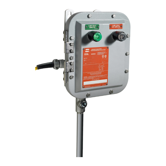
EGL Grounding Indicator with Automatic
Pump Control and Ground Verification System
Installation & Maintenance Information
APPLICATION
EGL Grounding Indicators are to be permanently mounted in a secure
location adjacent to loading/unloading area. EGL Grounding Indicators
are connected to tank vehicles, drums, or other containers before
beginning transfer of combustible materials. While connected, the EGL
grounds static electricity and continuously verifies the presence of a static
grounding system. The EGL can be installed to actuate remote devices
(lights, horns) to announce that a safe static ground has been
established, or to send an alarm when the ground is interrupted. An EGL
Grounding Indicator is recommended to be used in the control circuit of a
pump to prevent it from being started until the static grounding circuit is
completed, and to shut down the pump automatically if the static
grounding circuit is disconnected.
INSTALLATION
To provide protection against fire or shock hazard, the electrical
power must be OFF before and during installation and
maintenance.
To ensure proper operation of the EGL210, two separate ground
leads from the electrical supply panel must be provided: one to
terminal #3 and the other to the green ground lug on the
enclosure interior. This provides a continuity check to verify the
EGL210 is grounded.
WEIGHT = 32 lbs (14.5 kg)
IF 1512 • 11/11
SAVE THESE INSTRUCTIONS FOR FUTURE REFERENCE
WARNING
CAUTION
DIMENSIONS - INCHES (CENTIMETERS)
Copyright © 2011, Cooper Industries, Inc.
EGL Grounding Indicators are suitable for use in Class I, Groups B, C, D;
Class II, Groups F, G, and Class III hazardous (classified) areas as
defined by the National Electrical Code (NEC).
EGL Grounding Indicators should be installed, inspected, and serviced by
qualified and competent personnel.
Read all instructions before starting installation of this product.
Contact your Crouse-Hinds sales representative, Customer Service, or
your Crouse-Hinds distributor if you have any questions.
1.
Select a mounting location that will provide suitable strength and
rigidity for supporting the enclosure, all contained wiring and
control devices. Figure 1 shows mounting dimensions.
•
Hazardous location information specifying Class and Group
listing is marked on the enclosure nameplate.
•
Conduit sealing fittings must be installed in accordance
with Section 501 of the National Electrical Code. An
appropriate seal shall be installed within 18" (45.7 cm) of the
enclosure for Groups B.
•
All unused conduit openings must be plugged. Plug must
engage a minimum of five full threads and be a minimum of
1/8" (.318 cm) thick.
FIGURE 1
IF 1512
CAUTION
Page 1
Publicidad
Tabla de contenido

Resumen de contenidos para Cooper CROUSE-HINDS EGL Serie
- Página 1 EGL210 is grounded. 1/8“ (.318 cm) thick. WEIGHT = 32 lbs (14.5 kg) FIGURE 1 DIMENSIONS - INCHES (CENTIMETERS) IF 1512 • 11/11 Copyright © 2011, Cooper Industries, Inc. Page 1...
- Página 2 PRIMARY LINE 1 LINE 2 CONNECTION CONNECT VOLTAGE CONNECTION #1 & #4 #1 & #2 #3 & #4 EGL210 GROUND INDICATOR FIELD WIRING FIGURE 2 - WIRING DIAGRAM IF 1512 • 11/11 Copyright © 2011, Cooper Industries, Inc. Page 2...
-
Página 3: Replacement Parts
In accordance with Crouse-Hinds "Terms and Conditions of Sale", and since conditions of use are outside our control, the purchaser should determine the suitability of the product for his intended use and assumes all risk and liability whatsoever in connection therewith. Cooper Industries Inc., Crouse-Hinds Division IF1512... - Página 4 ENTRÉE DE TUBE PROTECTEUR 1" (254) AVEC RACCORD RÉDUCTEUR ¾" (1,91) 8.41 (21.36) 6.30 (16.00) POIDS = 32 lb (14,5 kg) 3.00 (7.62) 1.75 (4.45) ILLUSTRATION 1 DIMENSIONS - POUCES (CENTIMÈTRES) IF 1512 • 11/11 Copyright © 2011, Cooper Industries, Inc. Page 4...
- Página 5 #1 & #4 ROUGE NARA #3 & #4 #1 & #2 NOIR INDICATEUR DE MISE À LA TERRE POUR CÂBLAGE D’EXCITATION GL210 ILLUSTRATION 2 — DIAGRAMME DE CÂBLAGE IF 1512 • 11/11 Copyright © 2011, Cooper Industries, Inc. Page 5...
-
Página 6: Pièces De Rechange
Cooper Industries Inc., division Crouse-Hinds IF1512 Boîte postale 4999 Révision 3 Syracuse, New York 13221 • États-Unis Revised 11/11 Tous droits réservés© 2011, Cooper Industries, Inc. Supercedes 11/08... -
Página 7: Instalación
Contacte con su Representante de Ventas, con el Servicio al Cliente, o estática se haya completado, y para apagar la bomba automáticamente si con su Distribuidor de Cooper Crouse-Hinds en caso de tener alguna el circuito de puesta a tierra estática se desconecta. - Página 8 CONEXION CONECCION #1 & #4 NARA #1 & #2 #3 & #4 CABLEADO DEL INDUCTOR DEL INDICADOR DE PUESTA A TIERRA EGL210 FIGURA 2. - DIAGRAMA DE CABLEADO IF 1512 • 11/11 Copyright © 2011, Cooper Industries, Inc. Página 8...
-
Página 9: Instalación Del Conjunto De La Abrazadera De Repuesto Eglk1
De acuerdo con los "Términos y condiciones de venta" de Crouse-Hinds, y ya que las condiciones de uso están fuera de nuestro control, el comprador debe determinar la conveniencia del producto para el uso que le desee dar y asume todos los riesgos y obligaciones. Cooper Industries Inc., Crouse-Hinds Division IF1512 PO Box 4999 Revisión 3...
