Publicidad
Idiomas disponibles
Idiomas disponibles
Enlaces rápidos
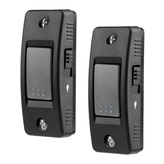
PUSH BUTTON DOOR CONTROL
Model 883LM
For use with Security✚ 2.0
TM
Garage Door Openers. All
TM
Security✚ 2.0
Garage Door Openers have a yellow
Learn button and a yellow antenna wire.
To prevent possible SERIOUS INJURY or DEATH from
electrocution:
• Be sure power is NOT connected BEFORE installing
door control.
• Connect ONLY to 12 VOLT low voltage wires.
To prevent possible SERIOUS INJURY or DEATH from
a closing garage door:
• Install door control within sight of garage door, out
of reach of children at a minimum height of 5 feet
(1.5 m), and away from ALL moving parts of door.
• NEVER permit children to operate or play with door
control push buttons or remote control
transmitters.
• Activate door ONLY when it can be seen clearly, is
properly adjusted, and there are no obstructions to
door travel.
• ALWAYS keep garage door in sight until completely
closed. NEVER permit anyone to cross path of
closing garage door.
NOTICE: To comply with FCC and or Industry Canada rules (IC),
adjustment or modifi cations of this receiver and/or transmitter are
prohibited, except for changing the code setting or replacing the
battery. THERE ARE NO OTHER USER SERVICEABLE PARTS.
Tested to Comply with FCC Standards for Home or offi ce use.
Operation is subject to the following two conditions: (1) this device
may not cause harmful interference, and (2) this device must accept
any interference received, including interference that may cause
undesired operation.
This Class B digital apparatus complies with Canadian ICES-003.
Cet appareil numérique de la classe B est conforme à la norme NMB-
003 du Canada.
Installation
Unplug the garage door opener.
1
Strip 1/4" (6 mm) of insulation from one
2
end of the wire and separate the wires.
Connect one wire to each of the two screws
3
on the back of the door control. The wires
can be connected to either screw.
Mount the door control with the hardware
4
provided.
Run the white and red/white wire from the
5
door control to the garage door opener.
Attach the wire to the wall and ceiling with
the staples (if applicable).
7/16" (11 mm)
1/4" (6 mm)
PRE-WIRED INSTALLATIONS: Choose any two
wires to connect, but make note of which wires
are used so that the correct wires are connected
to the garage door opener.
Strip 7/16" (11 mm) of insulation from the
6
other end of the wire near the garage door
opener.
Connect the wire to the red and white
7
terminals on the garage door opener.
Reconnect power to the garage door
8
opener. The LED behind the Push button on
the door control will blink if installed
correctly.
9
To synchronize the door control to the
garage door opener, press the push button
until the garage door opener activates (it
may take up to 3 presses). Test the door
control by pressing the push button, each
press of the push button will activate the
garage door opener.
To insert or release wire, push in
tab with screwdriver tip.
Do not pierce the wire
with the staple as this
may cause a short or an
open circuit.
Programming
TO ADD, REPROGRAM, OR CHANGE A REMOTE
CONTROL/KEYLESS ENTRY PIN USING THE
DOOR CONTROL
1
Press and hold the Light button and the Push
button until the Push button LED begins to
blink.
Light Button
Push Button
2a
Press the button on the remote control that
you wish to operate your garage door.
OR
2b
Enter a 4-digit personal identification number
(PIN) of your choice on the keyless entry
keypad. Then press the ENTER button.
?
?
?
?
PIN
The garage door opener lights will flash (or two
clicks will be heard) when the code has been
programmed.
Publicidad

Manuales relacionados para LiftMaster 883LM


Resumen de contenidos para LiftMaster 883LM
- Página 1 Strip 7/16" (11 mm) of insulation from the TO ADD, REPROGRAM, OR CHANGE A REMOTE other end of the wire near the garage door CONTROL/KEYLESS ENTRY PIN USING THE Model 883LM opener. DOOR CONTROL Strip 1/4" (6 mm) of insulation from one end of the wire and separate the wires.
- Página 2 POUR AJOUTER, REPROGRAMMER OU BOUTONS-POUSSOIRS l'autre extrémité du fil, près de l'ouvre-porte MODIFIER UN NIP DE TÉLÉCOMMANDE OU Modèle 883LM de garage. Enlevez 6 mm (1/4 po) d'isolation à DE COMMANDE DE TÉLÉDÉVERROUILLAGE À l'extrémité du fil, puis séparer les fils.
- Página 3 PARA AGREGAR, REPROGRAMAR O CAMBIAR PULSADOR aislamiento del extremo del cable del lado UN CONTROL REMOTO O NÚMERO DE PIN DEL Modelo 883LM del abre-puerta. Quitar 1/4 de pulg. (6 mm) de aislamiento TECLADO CON EL CONTROL FIJO DE PUERTA...
- Página 4 © 2012, The Chamberlain Group, Inc. 1-800-528-9131 114A4394B All Rights Reserved Tous droits réservés Todos los Derechos Reservados...