Publicidad
Enlaces rápidos
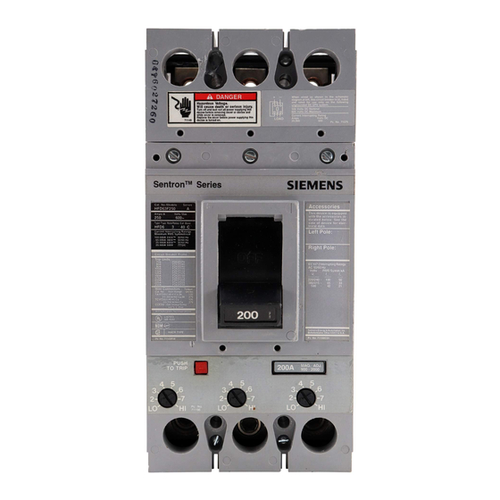
FD Frame types FD6-A, FXD6-A, HFD6, HFXD6,
Devices:
HHFD6, HHFXD6 and CFD6 Circuit Breakers; types
FD6-ETI and CFD6-ETI Motor Circuit Interrupters; and
types FXD6, HFXD6, and CFD6 Molded Case
Switches.
1 of 3
Page
81962A03
Pc. No.
Siemens Energy & Automation, Inc.
Bellefontaine, OH 43311 U.S.A.
Installation Instructions
Hazardous voltage.
Will cause death or serious injury.
Turn off and lock out all power supplying this
device before removing cover or device and while
cover is removed.
Replace the cover before power supplying this
device is turned on.
SAFETY INSTRUCTIONS
NOTE: This instruction outlines the recommended
installation procedure.
INTRODUCTION
The FD Frame circuit breaker line includes types-FD6-A,
FXD6-A, HFD6, HFXD6, HHFD6, HHFXD6 and CFD6 Circuit
Breakers; types-FD6-ETI and CFD6-ETI Motor Circuit
Interrupters; and Types FXD6, HFXD6, and CFD6 Molded
Case Switches. These devices are rated for operating volt-
ages up to 600 VAC, 50/60 Hz.
INSTALLATION
FD frame devices are for use in individual enclosures, panel
boards, switchboards or other approved equipment.
The installation procedure consists of inspecting, attaching
required accessories, mounting the device and connecting
and torquing the line and load wire connectors.
Mounting hardware and unmounted wire connectors (where
required) are available as separate catalog items.
Note: Trip unit and accessory installation should be
completed before the device is mounted and connected. (See
installation instructions supplied with trip unit and accessory
before proceeding).
Note: Motor circuit interrupters and molded case switches
are supplied as complete devices only.
Note: Molded case switches do not have a PUSH-TO-TRIP
button.
A. Turn off and lock out all power before installing or servicing.
B. Make sure that the device is suitable for the installation
by comparing nameplate ratings with system require-
ments. Inspect the device for completeness and check for
any damage before mounting.
Interruptores termomagnéticos Marco FD, Tipo-FD6-
A, FXD6-A, HFD6, HFXD6, HHFD6, HHFXD6 y
CFD6; Interruptores, Tipo FD6 ETI y CFD6 ETI; y
Interruptores mobibles, Tipo FXD6, HFXD6, y
CFD6.
Instructivo de Instalación y Operación
Tensión peligrosa que puede causar
daños serio o la muerte, desenergice
totalmente antes de instalar o darle
servicio. Reemplace todas las barreras
y cubiertas antes de energizar el
interruptor.
INSTRUCCIONES DE SEGURIDAD
Lea cuidadosamente este instructivo, con ello obtendrá la
completa seguridad en el uso de estos equipos para su montaje.
1 Información Técnica
Generalidades
La línea de interruptores termomagnéticos Tipo FD6-A, FXD6-A,
HFXD6, HFD6, HFXD6, HHFD6, HHFXD6 y CFD6; Interrup-
tores, Tipo FD6 ETI y CFD6 ETI; y Interruptores mobibles, Tipo
FXD6, HFXD6 y CFD6, para corrientes nominales desde 150
hasta 250 A, son adecuados para operar en tensiones hasta 600 V
C.A. 50/60 Hz.
2 Instalación.
Los interruptores termomagnéticos FXD6, están previstos para
alojarse en gabinetes individuales, tableros de distribución,
tableros de alumbrado y otros gabinetes aprobados.
El procedimiento para la instalación consiste de: inspección de los
accesorios requeridos, montaje del interruptor y conexión de los
conductores del lado de línea y de carga. Montaje de los
conectores para cable o solerás (Cuando se requieran).
La unidad de disparo y los accesorios de instalación, deben estar
completas antes que el interruptor sea instalado y conectado.
Cuando el interruptor es de unidad de disparo intercambiable, esta
se suministra junto con los accesorios necesarios.
A. Desenergice totalmente antes de instalarlo o darle mantenimien-
to.
B. Asegúrese que el interruptor sea el adecuado para la protección
del circuito en el que se instala, consultando las especificaciones
en la placa de características.
Peligro
Publicidad

Manuales relacionados para Siemens FD Serie


Resumen de contenidos para Siemens FD Serie
- Página 1 Interruptores mobibles, Tipo FXD6, HFXD6, y Switches. 1 of 3 Page CFD6. 81962A03 Pc. No. Siemens Energy & Automation, Inc. Bellefontaine, OH 43311 U.S.A. Installation Instructions Instructivo de Instalación y Operación Peligro Hazardous voltage. Tensión peligrosa que puede causar Will cause death or serious injury.
- Página 2 D. Para la instalación del interruptor favor de considerar lo siguiente. 1. For individual enclosures, panelboards and switch- boards manufactured by Siemens Energy & Automation, 1. Seguir las instrucciones dadas con el suministro de este Inc., follow the instructions provided with this equipment.
- Página 3 Replace the cover before power supplying this device is turned de energizar el interruptor. 3 of 3 Page © Siemens Energy & Automation, Inc. 1993 81962A03 Pc. No. Installation Instructions Instructivo de Instalación y Operación MANUAL OPERATION 3 Operación manual.