
Manuales relacionados para Televes M550XL


Resumen de contenidos para Televes M550XL
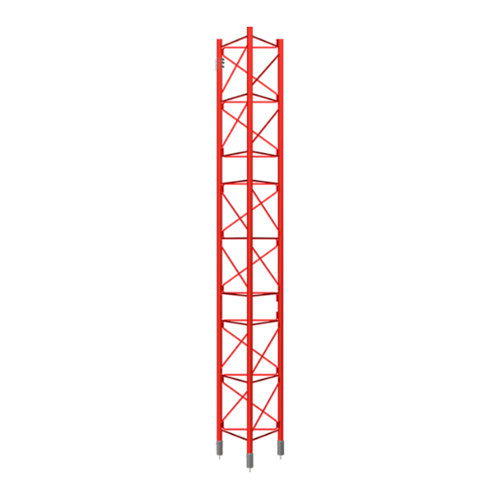
- Página 1 M550XL Instrucciones de montaje TORRE ARRIOSTRADA Assembling instructions GUYED TOWER w w w . t e l e v e s . c o m...
- Página 3 IMPORTANTE Las instalaciones de torretas deberán ser calculadas y ejecutadas sólo por profesio- nales especializados y bajo su propia responsabilidad. Las instrucciones de montaje que se dan en este documento son a título indicativo y los datos facilitados no compro- meten en ningún caso la responsabilidad del fabricante, que sólo garantiza sus propios fabricados siempre y cuando éstos se utilicen en las condiciones normales de uso.
-
Página 4: Descripción De Referencias
Referencia 313921 La torre es de base triangular y está formada por elementos estándar de 3m Descripción Tramo inferior torre M550XL, Color rojo (RAL 3020). cada uno. (1) Acero S355- Ø 50 x 6 mm esp. Re min. 355 N/mm - Rn. - Página 5 Peso 120Kg Referencia 313820 Descripción Tramo superior torre M550XL, Color rojo (RAL 3020). (1) Acero S355 JR Ø 50 x 3 mm espesor Re min. 355 N/mm - Rn. 510 N/mm (2) Acero S275JR Ø 14 mm Re min. 275 N/mm - Rn.
-
Página 6: Sistema Anclaje De Vientos
43634 N R=25.0000 m 587649 N (Axial) R=40.0000 m 776 N-m (Torque) R=55.0000 m R=70.0000 m ALL REACTIONS ARE FACTORED R=80.0000 m R=90.0000 m Televes Job: 138m_550E_160Kmh_PROBA_v2 Rua B. Conxo Project: Client: Drawn by: App'd: manlag Santiago de Compostela Code:... -
Página 7: Cimentación Hormigón
8.1 Cimentación hormigón Las cimentaciones (que tienen un carácter orientativo) se han estimado para una resistencia admisible del terreno de 1,5 Kg/cm , aunque podrían aceptarse terrenos con resistencia admisible de 1Kg/cm El hormigón a emplear tendrá una resistencia característica mínima de 15 N/ . -
Página 8: Placas De Enterrar
TORRE 550XL 8.2 Placas de enterrar 8.2.1 Cálculo zapata enterrar Ref. 314501 / 354511 A.- Área de la zapata en m²= 1m² / 2,25 m² ð.- Densidad del terreno; ( entre 13000 y 18000 N/m³, dependiendo del terreno y su compactación) µ.- Coeficiente de rozamiento de la zapata con el terreno ( Suponemos µ=0,5) TV.- Componente vertical del tiro de los vientos en N TH.- Componente horizontal del tiro de los vientos en N... - Página 9 9. Estructura (tramos/vientos) 6 x d Los sujetacables deben reapretarse una vez el ca- ble haya sido sometido a la primera tracción. El cuerpo del sujetacable debe montarse sobre la parte activa del cable, tal como indica la figura. Detalles de ensamblaje de la torre y detalle orientativo del tensado de los vientos...
- Página 10 TORRE 550XL Paso 1 Paso 2 Superior Paso 3 Paso 4 Cada tramo irá embutido con el anterior con un pasador de seguridad de Ø10 mm por pata. Una vez montado el pasador, se debe cerrar la anilla de seguridad para evitar que este se salga.
-
Página 11: Señalización
10. Señalización Los métodos indirectos De acuerdo con las normas de la O.A.C.I. (Organización Internacional de Avia- Existen dos técnicas habituales para medir de forma indirecta la tensión inicial ción Civil), los tramos deberán colocarse alternativamente en colores aeronáu- de los cables de vientos: el método de pulso o de oscilaciones (vibraciones) ticos blanco y rojo, siendo de este último color los extremos, con el fin de ser y el método de la intersección de la tangente o de combado (geométrico). - Página 12 TORRE 550XL + (V-I) + (V-I) Wi = Peso del segmento i, en Newtons. Ci = Distancia horizontal desde la sujeción del cable a la torre hasta el centro de gravedad del segmento, en m. N = Número de segmentos + (V-I) Si es difícil de fijar el punto de intersección, se puede utilizar la pendiente del cable en el punto de anclaje con la siguiente ecuación:...
- Página 15 IMPORTANT The installation of masts must be calculated and carried out by specialised personnel and under their own responsibility. The assembling instructions provided in this docu- ment are indicators and the data provided in no way encumbers the manufacturer or makes them responsible.
-
Página 16: Reference Description
The tower has a triangular base and is made up of standard elements, each measuring 3.0 m. Description Reinforced bottom section M550XL In Red (RAL 3020) Each element is made up of: (1) S355 Steel Ø 50 x 6 mm. - Página 17 Weight 120kg 313820 Reference Description M550XL Tower upper section. Red (RAL 3020) (1) S355 JR steel Ø 50 x 3 mm thickness Re min. 355 N/mm - Rn. 510 N/mm (2) S 275JR steel Ø 14 mm Re min. 275 N/mm - Rn.
- Página 18 M550XL TOWER 8. Wind anchorage system Behavior example of the tower. 138.0 m R=90.0000 m R=90.0000 m 137.6 m 136.0 m R=80.0000 m R=80.0000 m 134.0 m R=70.0000 m R=70.0000 m 132.0 m 130.0 m R=55.0000 m R=55.0000 m R=55.0000 m 128.0 m...
- Página 19 8.1 Foundations The foundations (which are merely a guide) have been estimated on an admis- sible load resistance of 1.5 kg/cm2, although it may also be applicable to grounds with an admissible load resistance of 1kg/cm2. The cement used will have a minimum characteristic resistance load of 15 N/ mmm2.
- Página 20 M550XL TOWER 8.2 Anchor fundation plate 8.2.1 Footing calculation Ref. 314501 / 354511 A.- Footing area in m²= 1m² / 2,25 m² ð.- Ground density; ( entre 13000 y 18000 N/m³, depending on the ground and its compaction) µ.- Coefficient of friction (footing with the ground). Suppose µ=0,5) TV.- Vertical component guys uplift force in N...
- Página 21 9. Structure (sections/ guy-wires) 6 x d The cable clips must be retightened once the cable has undergone the first traction. The body of the cable clamp must be fixed over the active part of the cable, as shown in the diagram. Tower assembling details and guy wire tension guide...
- Página 22 M550XL TOWER Step 1 Step 2 Step 3 Step 4 Each section will be embedded with the previous one with a Ø10 mm safety pin. Once the safety linch pin is mounted, the safety clip must be closed to prevent it from falling out.
-
Página 23: Important Advice
10. Signalling The Indirect Methode In accordance with the ICAO (International Civil Aviation Organisation), the sec- There are two common techniques for the indirect measurements of guy initial tions must be assembled in alternating aeronautic colours, white and red, the tensions;... - Página 24 + (V-I) + (V-I) Wi = Weight of segment i, in Newton. Ci = Horizontal distance from the guy attachment on the tower to the center of gravity of segment, in m. N = Number of segments. + (V-I) If the intercept is difficult to establish, one may use the guy slope at the anchor end with the following equation: + (V-I) 1+tan...
- Página 26 M550XL TOWER...