Publicidad
Idiomas disponibles
Idiomas disponibles
Publicidad
Tabla de contenido

Manuales relacionados para AmazonBasics B00MIBN16O


Resumen de contenidos para AmazonBasics B00MIBN16O
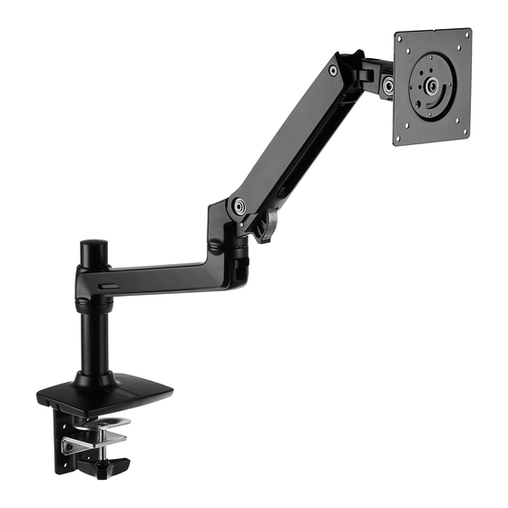
- Página 1 AmazonBasics Desk Monitor Mount B00MIBN16O...
- Página 2 English ..... .3 Français ....17 Deutsch .
- Página 3 English Instruction Manual · English AmazonBasics Desk Monitor Mount Contents Make sure that the package contains the following parts: Lower arm Grommet bracket (1 pc) (1 pc) Upper arm (1 pc) Base (1 pc) M4 × 10 mm screw (4 pcs)
- Página 4 Supported monitor weights Your monitor mount supports a monitor of the following weight: 5 to 25 lbs (2.3 to 11.3 kg) Monitor adjustments Your monitor mount lets you adjust the monitor viewing angle, height, tilt, and orientation (portrait or landscape). 360°...
- Página 5 Assembly Instructions Caution: Because mounting surface materials can vary widely, make sure that the mounting surface is strong enough to handle your monitor mount and the monitor. Step 1: Choose a mounting option. You can mount the monitor arm using the: •...
- Página 6 Desk-clamp mount Step A: Determine the thickness of the mounting surface, then use the 4 mm Allen wrench to adjust the location of the mounting clamp assembly, if necessary. • The top screw holes on the clamp bracket fit a mounting surface thickness of less than 5/8 in.
- Página 7 Plate mount Step A: Remove the mounting clamp assembly from the clamp bracket on the base. 4 mm Step B: Remove the clamp bracket from the base. Keep the screws you remove. You will use them later. 4 mm Step C: Make sure that the side of the grommet bracket with recessed screw holes is facing down.
- Página 8 Step D: Attach the grommet bracket to the base with the 3 screws you removed from the clamp bracket. Note: If the screws are not flush to the grommet bracket, the grommet bracket is upside down. Remove these screws and the M8 × 3 in. screw, turn the grommet bracket over, then put all the screws back in.
- Página 9 Step 2: Determine the orientation of the monitor You can mount the monitor in a locked portrait or landscape orientation, or you can leave the monitor free to rotate 360°. • If you want the monitor to rotate freely, do not insert the M3 x 6 mm screw. •...
- Página 10 Step 3: Attach the upper arm to the back of the monitor using a Phillips screwdriver. Note: If a stand is attached to the monitor, remove the stand. Note: You can use the M4 × 10 mm screws or M4 × 10 mm knobs to attach the arm to the monitor.
- Página 11 Step 4: Slide the lower arm onto the base. Slide the upper arm over the lower arm, then insert the bracket cover into the top of the upper arm. The cover should snap into place. Note: To remove the bracket cover, use a flathead screwdriver to pry off the cover. Bracket cover Note: If the monitor is too high or too low, remove the upper and lower arms.
- Página 12 Step 5: Insert the cable ties through the loops on the bottom of the upper arm, route the monitor cables along the upper arm, then loosely secure the cables to the upper arm with the cable ties. Do not over-tighten the ties. If the ties are too tight and you try to remove them, you may damage the monitor cables.
- Página 13 Step 6: Adjust your monitor mount's tension. You can adjust the vertical, tilt, and arm tension so that the monitor stays in place when you move it. Adjusting the vertical tension Tilt the monitor down to access the screw. If the monitor is rising up, loosen the screw by turning it to the left.
- Página 14 Adjusting the tilt tension If the monitor is falling forward (screen goes down), loosen the screw by turning it to the left. If the monitor is falling back (screen goes up), tighten the screw by turning it to the right. Caution: Do not remove the screw.
- Página 15 Adjusting the arm tension To make the arm easier to move, loosen the screws by turning them to the left. To make the arm harder to move, tighten the screws by turning them to the right. Caution: Do not remove the screws. The monitor might fall.
-
Página 16: Safety And Compliance
Depending on your product and the adjustment, it may take many turns to notice a difference. © 2014 Amazon.com, Inc. or its affiliates. All Rights reserved. Amazon and the AmazonBasics logo are trademarks of Amazon.com, Inc. or its affiliates. - Página 17 Français Manuel d’utilisation · Français Support de Bureau pour Moniteur AmazonBasics Contenu Assurez-vous que l’emballage contient les pièces suivantes : Bras inférieur Plaque de fixation (1 pce) passe-câble Bras supérieur (1 pce) (1 pce) Base (1 pce) Vis M4 x 10 mm...
- Página 18 Le moniteur supporté pèse Votre support de moniteur supporte un moniteur de poids suivant : 2,3 a 11,3 kg (5 à 25 lb) Réglages du moniteur Votre support de moniteur vous laisse régler l’ange de vue, la hauteur, l’inclinaison, et l’orientation (portrait ou paysage).
- Página 19 Notice d’assemblage Attention : Puisque que les matériaux de surface peuvent varier largement, assurez-vous que la surface de montage est suffisamment solide pour supporter votre support de moniteur et le moniteur. Étape 1 : Choisissez une option de montage. Vous pouvez monter le bras de moniteur en utilisant le : •...
- Página 20 Support à pince de bureau Étape A : Déterminez l’épaisseur de la surface de montage, puis utilisez la clé hexagonale de 4 mm pour régler l’emplacement de l’ensemble pince de montage, si nécessaire. • Les trous de vis du haut sur la plaque de fixation de pince conviennent pour une épaisseur de surface de montage de moins de 1,6 cm (5/8 po).
-
Página 21: Support De Plaque
Support de plaque Étape A : Retirez l’ensemble pince de montage du support de pince sur la base. 4 mm Étape B : Retirez le support de pince de la base. Gardez les vis que vous enlevez. Vous les utiliserez plus-tard. 4 mm Étape C : Assurez-vous que le côté... - Página 22 Étape D : Attachez la plaque de fixation passe-câble à la base avec les 3 vis que vous avez enlevées du support pince. Remarque : Si les vis ne sont pas au même niveau que la plaque de fixation passe-câble, la plaque de fixation passe-câble est à...
- Página 23 Étape 2 : Déterminez l’orientation du moniteur Vous pouvez monter le moniteur dans une orientation portrait ou paysage verrouillée, ou vous pouvez laisser le moniteur libre de tourner 360°. • Si vous voulez que le moniteur tourne librement, n’insérez pas la vis M3 x 6 mm. •...
- Página 24 SÉtape 3 : Attachez le bras supérieur au dos du moniteur en utilisant un tournevis cruciforme. Remarque : Si un socle est attaché au moniteur, retirez le socle. Remarque : Vous pouvez utiliser les vis M4 x 10 mm ou boutons M4 x 10 mm pour attacher le bras au moniteur.
- Página 25 Étape 4 : Glissez le bras inférieur sur la base. Glissez le bras supérieur au-dessus du bras inférieur, puis insérez le couvercle de plaque de fixation dans le haut du bras supérieur. Le couvercle devrait s’emboîter en place avec un clic. Remarque : Pour enlever le couvercle de plaque de fixation, utilisez un tournevis à...
- Página 26 Étape 5 : Insérez les attaches de câbles à travers les boucles sur le bas du bras supérieur, acheminez les câbles du moniteur le long du bras supérieur, puis attachez sans serrer les câbles au bras supérieur avec les attaches de câbles. Ne pas trop serrer les attaches de câbles.
- Página 27 Étape 6 : Réglez la tension de votre support de moniteur. Vous pouvez régler la tension verticale, d’inclinaison, et de bras pour que le moniteur reste en place quand vous le déplacez. Réglage de la tension verticale Inclinez le moniteur vers le bas pour avoir accès aux vis. Si le moniteur s’élève, desserrez la vis en la tournant vers la gauche.
- Página 28 Réglage de la force de basculement Si le moniteur bascule vers l’avant (l’écran descend), desserrez la vis en la tournant vers la gauche. Si le moniteur bascule vers l’arrière (l’écran s’élève), serrez la vis en la tournant vers la droite. Attention : Ne pas enlever les vis.
- Página 29 Réglage de la tension du bras Pour rendre le bras plus facile à déplacer, desserrez les vis en les tournant vers la gauche. Pour rendre le bras plus difficile à déplacer, serrez les vis en les tournant vers la droite. Attention : Ne pas enlever les vis.
-
Página 30: Sécurité Et Conformité
Suivant votre produit et le réglage, cella peut demander de nombreux tours pour remarquer une différence. © 2014 Amazon.com, Inc. ou ses filiales. Tous droits réservés. Amazon et le logo AmazonBasics sont des marques de commerce d’Amazon.com, Inc. ou de ses fi liales. - Página 31 Deutsch Bedienungsanleitung · Deutsch AmazonBasics Monitorhalterung zur Schreibtischmontage Inhalt Bitte stellen Sie sicher, dass das Paket die folgenden Teile enthält: Unterer Arm Schraubhalterung (1 Stck.) (1 Stck.) Oberer Arm (1 Stck.) Fuß (1 Stck.) M4 × 10 mm Schraube (4 Stck.) Abdeckung (1 Stck.)
- Página 32 Unterstützte Monitorgewichte Die Monitorhalterung unterstützt einen Monitor mit folgendem Gewicht: 2,3 bis 11,3 kg Monitoreinstellungen Die Monitorhalterung ermöglicht die Einstellung des Sichtwinkels, der Höhe, der Neigung und der Ausrichtung (vertikal oder horizontal) des Monitors. 360° 70° 360° 13 in. (330 mm) 180°...
- Página 33 Montageanleitung Vorsicht: Da die Beschaffenheit der Montageoberflächen sehr unterschiedlich sein kann, muss sichergestellt werden, dass die Montageoberfläche stark genug ist, um die Monitorhalterung mit Monitor zu halten. Schritt 1: Auswahl einer Montageoption. Der Monitorarm kann auf folgende Weise montiert werden: •...
- Página 34 Schreibtisch-Klemmmontage Schritt A: Die Dicke der Montageoberfläche bestimmen und dann den 4 mm Imbusschlüssel verwenden, um ggf. die Montageklemme einzustellen. • Die oberen Schraublöcher an der Klemmhalterung sind passend für eine Oberflächendicke von weniger als 1,6 cm. • Die mittleren Schraublöcher an der Klemmhalterung sind passend für eine Oberflächendicke von 0,6 bis 4,1 cm.
- Página 35 Tischplattenmontage Schritt A: Die Montageklemme von der Klemmhalterung am Fuß abnehmen. 4 mm Schritt B: Klemmhalterung vom Fuß abnehmen. Die abgenommenen Schrauben aufbewahren. Sie werden später benötigt. 4 mm Schritt C: Sicherstellen, dass die Seite der Schraubhalterung mit den eingesenkten Schraublöchern nach unten zeigt.
- Página 36 Schritt D: Schraubhalterung mit den 3 Schrauben, die von der Klemmhalterung abgenommen wurden, am Fuß befestigen. Hinweis: Wenn die Schrauben nicht bündig an der Schraubhalterung anliegen, wurde die Schraubhalterung verkehrt herum angebracht. In dem Falle müssen diese Schrauben und die M8 ×...
- Página 37 Schritt 2: Ausrichtung des Monitors Der Monitor kann in vertikaler oder horizontaler Ausrichtung fixiert oder unfixiert um 360° drehbar montiert werden. • Wenn der Monitor unfixiert und drehbar verwendet werden soll, darf die M3 x 6 mm Schraube nicht eingesetzt werden. •...
- Página 38 Schritt 3: Den oberen Arm an der Rückseite des Monitors mit einem Kreuzschraubenzieher befestigen. Hinweis: Wenn der Monitor einen Standfuß besitzt, muss dieser entfernt werden. Hinweis: Um den Arm am Monitor zu befestigen, können die M4 x 10 mm Schrauben oder die M4 x 10 mm Schraubknöpfe verwendet werden.
- Página 39 Schritt 4: Unteren Arm auf den Fuß schieben. Den oberen Arm über den unteren Arm schieben und dann die Abdeckung in die Oberseite des oberen Arms drücken. Die Abdeckung sollte einrasten. Hinweis: Um die Abdeckung zu entfernen, sie mit einem Flachschraubenzieher lockern und abheben.
- Página 40 Schritt 5: Die Kabelbinder durch die Ösen an der Unterseite des oberen Arms führen, die Monitorkabel am oberen Arm entlangführen und sie dann mit den Kabelbindern locker am oberen Arm befestigen. Die Kabelbinder nicht zu stramm ziehen. Wenn die Kabelbinder zu stramm sind und dann entfernt werden sollen, können die Monitorkabel beschädigt werden.
- Página 41 Schritt 6: Einstellen der Spannung der Monitorhalterung. Die vertikale, Neigungs- und Armspannung kann eingestellt werden, damit der Monitor an Ort und Stelle bleibt, wenn er bewegt wird. Einstellen der vertikalen Spannung Monitor nach unten neigen, um Zugriff auf die Schraube zu erhalten. Wenn sich der Monitor nach oben bewegt, die Schraube durch Linksdrehung lockern.
- Página 42 Einstellen der Neigungsspannung IWenn der Monitor nach vorn fällt (der Bildschirm senkt sich nach unten), die Schraube durch Linksdrehung lockern. Wenn der Monitor nach hinten fällt (der Bildschirm bewegt sich nach oben), die Schraube durch Rechtsdrehung festziehen. Vorsicht: Die Schraube nicht entfernen. Dadurch kann der Monitor herunterfallen.
- Página 43 Einstellen der Armspannung Damit sich der Arm leichter bewegen lässt, die Schrauben durch Linksdrehung lockern. Damit sich der Arm schwerer bewegen lässt, die Schrauben durch Rechtsdrehung festziehen. Vorsicht: Die Schrauben nicht entfernen. Dadurch kann der Monitor herunterfallen. Die Schrauben nicht zu fest ziehen. Dadurch kann der Monitor oder die Monitorhalterung beschädigt werden.
- Página 44 Bewegung zu erzielen. Je nach Produkt und Einstellung kann ein Unterschied eventuell erst nach mehreren Bewegungen und Drehungen festgestellt werden. © 2014 Amazon.com, Inc. oder seine verbundenen Unternehmen. Alle Rechte vorbehalten. Amazon und das AmazonBasics-Logo sind Marken von Amazon.com, Inc. oder seinenverbundenen Unternehmen. Hergestellt in China...
- Página 45 ìŽñ{åÍ 取扱説明書 · 日本語 Amazon ベーシック デスクモニターアーム 梱包されているもの 以下の部品がパッケージに含まれているかご確認ください : 下部アーム グロメットブラケット (1 個) (1 個) 上部アーム (1 個) ベース (1 個) M4 × 10 mm ネジ (4 個) ブラケットカバー (1 個) M8 (1/4-20UNC、7.62 cm (1 個) M3 x 6 mm ネジ 1 (個)...
- Página 46 許容重量 モニターアームの許容重量は以下の通りです。 2.3 ~ 11.3 kg モニターの調整 モニターアームでは、モニターの角度、高さ、チルト、回転(縦、横)を調整することができ ます。 360 度 70 度 360 度 13 in. (330 mm) 180 度 5 度 角度 高さ チルト 回転...
- Página 47 組立説明書 注意:設置表面の素材にばらつきがあるた め、設置表面がモニターアームとモニター の設置に十分耐えられることを確認してく ださい。 ステップ 1: 設置オプションを選択します。 以下の方法でモニターアームを設置することができます : • 卓上の端にモニターアームを取り付けるクランプ式。48 ページの「クランプ式」へ移動。 • 卓上の端から離れた場所にモニターアームを取り付けるグロメット式。s この設置オ プションは、設置表面に穴を開ける必要があります。49 ページの「グロメット式」 へ移動。...
- Página 48 クランプ式 ステップ A: 設置表面の厚さを測り、必要に応じて 4mm 六角レンチを使用し、クランプを取 り付ける場所を調整します。 • クランプブラケットの一番上のネジ穴は、厚さ 1.6 cm 未満の設置表面用です。 • クランプブラケットの真ん中のネジ穴は、厚さ 0.6 ~ 4.1 cm の設置表面用です。 • クランプブラケットの一番下のネジ穴は、厚さ 3.2 ~ 6.7 cm の設置表面用です。 4 mm 六角レンチ <1 cm 3.7 ~ 6.0 cm 1.2 ~ 3.56 cm ステップ B: 設置用クランプアセンブリを設置表面に差し入れ、クランプを締めます。 注意:卓上の端より先までモニターを回転させ...
- Página 49 グロメット式 ステップ A: ベースのクランプブラケットから設置用クランプアセンブリを取り外します。 4 mm ステップ B: ベースからクランプブラケットを取り外します。取り外したネジは後ほど使用す るため保管しておきます。 4 mm ステップ C: グロメットブラケットの埋め込まれたネジ穴のある面が下になるよう確認しま す。グロメットブラケットの中央にある四角い穴に M8 × 7.62 cm のネジを挿入します。 注記:ベースの中に 7.62 cm のネジが落ちないようにするため、一時的にウィングナットを 付け仮留めしておきます。...
- Página 50 ステップ D: クランプブラケットから取り外したネジ 3 本を使用し、ベースにグロメットブラ ケットを取り付けます。 注記:ネジがグロメットブラケットから見えない場合、グロメットブラケットは上下逆さまに なっています。そのネジと M8 × 7.62 cm ネジを取り外し、グロメットブラケットをひっくり 返し、すべてのネジを付け直します。 4 mm ステップ E: プラスドライバーを使用して、クランプアセンブリからクランププレートを取り 外します。 ステップ F: 設置表面の穴の上に対しベースを中心に配置し、設置表面の裏側から M8 × 7.62 cm のネジを取り外したクランププレートをスライドして差し入れます。ウィングナットを使 用してネジに対してクランププレートを固定します。 注記:M8 × 7.62 cm ネジは穴の中心に配置しなければなりません。 ~ 51 mm 57 mm 注意:アームをしっかりと固定し、装備の損傷 を避けるため、ベースとクランププレートは設...
- Página 51 ステップ 2: モニターの回転の決定 モニターを縦方向または横方向に固定したり、360 度自由に回転させるように調整することが できます。 • モニターを自由に回転させたい場合、M3 x 6 mm ネジは使用しないでください。 • モニターを固定させたい場合、M3 x 6 mm ネジを上部アームのプレートの前面に M3 x 6 mm ネジを挿入します。 モニターは縦または横に固定さ れます。 モニターを自由に回転するこ とができます。 注記:ネジを挿入し、上部アームにモニターを設置した後に、モニターの回転を変えたい場合 には、上部アームから一旦モニターを取り外し、M3 x 6 mm ネジを挿入するか、取り外しま す。...
- Página 52 ステップ 3: プラスドライバーを使用し、上部アームをモニターの裏面に取り付けます。 注記:モニターにスタンドが付いている場合には、そのスタンドを取り外します。 注記:アームをモニターに取り付ける際、M4 × 10 mm ネジか M4 × 10 mm ノブのどちらかを 使用することができます。 注意:モニターの裏面にある設置用のネジ穴に は、付属の M4 × 10 mm ネジやノブとは別の種 類のネジが必要となる場合があります。 • モニターのネジ穴の直径より大きいネジ を使用した場合、ネジ穴を損傷する恐れ があります。 • モニターのネジ穴の直径より小さいネジ を使用した場合、モニターがアームから 落下する原因となる恐れがあります。 • 長すぎるネジを使用した場合、モニター のインテリアを損傷する恐れがあります。 上部アームにモニターを取り付ける前に、モニ ターの裏面のネジ穴に付属のネジやノブが合う かどうか確認してください。付属のネジやノブ が合わない場合、モニター用の取扱説明書で正 しいネジの種類やサイズを確認してください。 ネジ、 または...
- Página 53 ステップ 4: ベースに下部アームを差し入れます。下部アームの上に上部アームを差し入れ、 上部アームの上にブラケットカバーを挿入します。カバーはぴったりとはまるようになってい ます。 注記:ブラケットカバーを取り外すには、マイナスドライバーでカバーを持ち上げるように取 り外します。 ブラケッ トカバー 注記:モニターの位置が高すぎたり、低すぎたりする場合、上部アームや下部アームを取り外 し調整します。2.5mm のレンチを使用して、ベースリングのネジを緩め、リングを上下にス ライドさせて調節した後、ネジを締めます。...
- Página 54 ステップ 5: 上部アームの下にあるループに結束バンドを差し入れ、上部アームに沿ってモニ ターケーブルを這わせます。結束バンドを使用し、余裕を持ってケーブルを上部アームに固定 します。結束バンドをきつく締めすぎないでください。結束バンドをきつく締めすぎた場合、 取り外す際にモニターケーブルに損傷を与える恐れがあります。 下部アームカバーのタブを両側から押して、カバーを取り外し、下部アームの下にモニター ケーブルを這わせ、カバーを付け直します。 注意:結束バンドを締める前に、一番高い位置 にモニターを調整します。この操作により、 モニターの移動 / 高さの調整の際、ケーブルに 十分な余裕ができます。...
- Página 55 ステップ 6: モニターアームのテンションの調整を行ないます。移動した際にその場所にモニ ターがその場所に固定されるよう、上下、チルト、アームテンションを調整することができま す。 上下テンションの調整 ネジに届くようモニターを下向きに傾けます。モニターを上に上げる場合、ネジを左に回し緩 めます。モニターを下に下げる場合、ネジを右に回し締めます。 注意:結束バンドを締める前に、一番高い位置 にモニターを調整します。この操作により、モ ニターの移動 / 高さの調整の際、ケーブルに十 分な余裕ができます。 4 mm...
- Página 56 チルトの調整 モニターを前に傾ける場合(画面が下向き) 、ネジを左に回し緩めます。モニターを後ろに傾 ける場合(画面が上向き) 、ネジを右に回し締めます。 注意: ネジを取り外さないでください。モニターが落 下する恐れがあります。 ネジをきつく締めすぎないでください。モニ ターやモニターアームに損傷を与える恐れがあ ります。 4 mm...
- Página 57 アームの調整 アームを動かしやすくするには、ネジを左に回して緩めます。アームを固定するには、ネジを 右に回して締めます。 注意: ネジを取り外さないでください。モニターが落 下する恐れがあります。 ネジをきつく締めすぎないでください。モニ ターやモニターアームに損傷を与える恐れがあ ります。 2.5 mm...
- Página 58 安全性とコンプライアンス 重要 : 本製品は、設置完了後にテンションの調整が必要となります。移動範囲を試したり、テ ンションの調整を行なう前に、すべての装備が本製品に対して適切に設置されていることを確 認してください。本製品に対し、重量の異なる装備を追加したり変更する場合は、必ずこの調 整手順を繰り返し、操作の安全性や最適性を確認します。本製品は、移動範囲内をスムーズか つ簡単に移動することができ、セットした場所に固定できるようになっています。製品がス ムーズに移動しない場合やセットした場所に固定できない場合、調整方法に従ってテンション を緩めたり、締めたりすることにより、スムーズかつ簡単に移動できるようにします。ご使用 の製品や調節の仕方により、違いを感じるまでに何度か調整を行なわなければならない場合が あります。 © 2014 Amazon.com, Inc.( ま た は関連会社 )。 無断複写 ・ 転載を 禁ず。 Amazon と Amazon ベ ー シ ッ ク の ロ ゴ は、 Amazon.com, Inc. ま た は関連会社 の...
- Página 59 ÷–Œƒ 使用说明书 · 中文 亚马逊倍思桌面显示器支架 目录 确保包装中包含下列零部件: 下支撑臂 孔眼托架 (1 件) (1 件) 上支撑臂 (1 件) 底座 (1 件) M4 × 10 毫米螺钉 (4 件) 托架盖 (1 件) M8 (1/4-20UNC, 7.62 厘米 (1 件) M3 x 6 毫米螺钉 (1 件) M4 ×...
- Página 60 支撑显示器重量 您的显示器支架可支撑以下重量的显示器: 公斤 2.3 到 11.3 公斤 显示器调节 您的显示器支架能让您调节显示器的观看角度、高度、倾斜度和方向 (人物或风景) 。 360° 70° 360° 13 in. (330 毫米 ) 180° 5° 观看角度 高度 倾斜度 方向...
- Página 61 安装说明 小心:因为安装表面材料之间可能有很大差异, 因此请确保安装表面的坚固程度足以承受您的显 示器支架和显示器。 第 1 步:选择一个安装方案。 您可以使用以下方案来安装显示器支撑臂: t 桌面夹式安装,将您的显示器支撑臂固定在桌面的边缘处。详情请参见第 62 页的 “桌 面夹式安装” 。 t 板式安装,将您的显示器支架固定在远离桌沿的地方。这个安装方案需要在安装表面上 钻一个孔。详情请参见第 63 页的 “板式安装” 。...
- Página 62 桌面夹式安装 步骤 A:确定安装表面的厚度,然后使用 4 毫米的通用扳手来调整固定夹具组件的位置 (若适用) 。 • 夹具托架顶部的螺孔适合厚度小于 1.6 厘米的安装表面。 • 夹具托架中间的螺孔适合厚度在 0.6 到 4.1 厘米之间的安装表面。 • 夹具托架底部的螺孔适合厚度在 3.2 到 6.7 厘米之间的安装表面。 4 毫米通用扳手 小于 1 厘米 3.7 到 6.0 厘米 1.2 到 3.56 厘米 步骤 B:将固定夹具组件滑动到安装表面上,然后拧紧夹具。 小心:不要将显示器旋转到桌沿以外。显示器的 重量可能会导致桌子翻到。...
- Página 63 板式安装 步骤 A:从底座的夹具托架上拆下固定夹具组件。 4 毫米 步骤 B:从底座上拆下夹具托架。保存好您拆下的螺钉。您稍后会用到它们。 4 毫米 步骤 C:确保带有嵌壁式螺钉孔眼托架一侧朝下。将 M8 × 7.62 厘米螺钉插到孔眼托架中间的 方孔中。 注意:为避免 7.62 厘米的螺钉掉进底座中,您可以暂时使用翼形螺帽来将其固定在正确位置。...
- Página 64 步骤 D 使用您从夹具托架上拆下来的 3 个螺钉将孔眼托架固定到底座上。 注意:如果螺钉无法与孔眼托架齐平,这说明您的孔眼托架是倒置的。拆下这些螺钉和 M8 × 7.62 厘米螺钉,翻转孔眼托架,然后重新固定所有螺钉。 4 毫米 步骤 E 使用十字螺丝刀从夹具组件上拆下夹板。 步骤 F:使底座中心位于安装表面上的钻孔顶部之上,然后从安装表面的底部将您拆下的夹板滑 到 M8 × 7.62 厘米螺钉上。用翼形螺帽将夹板旋转到螺钉上。 注意:M8 × 7.62 厘米螺钉必须位于螺孔的中心。 8 到 51 毫米 57 毫米 小心:为了固定支撑臂连接以及避免设备损坏, 底座和夹板必须接触到螺孔两侧的安装表面。...
- Página 65 第 2 步:确定显示器的方向。 您可以在安装显示器时将其锁定在人物或风景方向,或者您也可以让显示器自由旋转 360° 。 • 如果您希望让显示器自由旋转,您便不需要插入 M3 x 6 毫米螺钉。 • 如果您希望将显示器锁定在一个方向,将 M3 x 6 毫米螺钉插到上支撑臂金属板的前方。 显示器被锁定在人物或风景方向。 显示器可自由旋转。 注意:如果您插入了螺钉,但在将显示器安装到上支撑臂上之后希望改变显示器的方向,您需要 从上支撑臂上拆下显示器,并插入或取出 M3 x 6 毫米螺钉。...
- Página 66 第 3 步:使用十字螺丝刀将上支撑臂固定到显示器背面。 注意:如果显示器上连接了支架,先拆除支架。 注意:您可以使用 M4 × 10 毫米螺钉或 M4 × 10 毫米旋钮来将支撑臂固定在显示器上。 小心:显示器背面的安装螺孔可能需要使用与提 供的 M4 × 10 毫米螺钉或旋钮的类型或长度不 同的螺钉。 • 使用直径过大的螺钉将损坏显示器上的螺 孔。 • 使用过小或过短的螺钉可能导致显示器从 支撑臂上掉落。 • 使用过长的螺钉会使显示器内部受损。 在您将显示器连接到上支撑臂上之前,确保提供 的螺钉或旋钮适合显示器背面的螺孔。如果提供 的螺钉或旋钮不适合,参考显示器附带的文件以 查找正确的螺钉类型和尺寸。 M4 × 10 毫米螺钉 或 M4 × 10 毫米旋钮 警告:上支撑臂承受拉力,因此当您将...
- Página 67 第 4 步:将下支撑臂滑到底座上。将上支撑臂滑动到下支撑臂的上方,将托架盖插入上支撑臂 的顶部。托架盖应扣响到位。 注意:如需拆下托架盖,使用一字螺丝刀将托架盖撬开。 托架盖 注意:如果显示器过高或过低,拆下上、下支撑臂。使用 2.5 毫米扳手松开底圈上的螺钉,将底 圈向上或向下滑动,然后拧紧螺钉。...
- Página 68 第 5 步:将束线带穿过上支撑臂底部的环,沿着上支撑臂布置显示器线缆,然后用束线带松散 地将线缆固定在上支撑臂上。不要将束线带系的过紧。如果束线带系的过紧,当您尝试移动它们 时,您便有可能损坏显示器线缆。 挤压下支撑臂盖子上的突出部分以拆下盖子,沿着下支撑臂底部布置显示器线缆,然后重新盖上 盖子。 小心:在您尝试系紧束线带之前,将您的显示器 调整到最高位置。这将留下足够的线缆长度,以 使显示器能自由移动 / 进行高度调节。...
- Página 69 第 6 步:调节您的显示器支架的张力。您可以调节垂直张力、倾斜张力和支撑臂张力,以使显 示器在移动时也能保持正确位置。 调节垂直张力 向下倾斜显示器,以便调节螺钉。如果显示器升起,向左旋转来松开螺钉。如果显示器下降,向 右旋转来拧紧螺钉。 小心:在您尝试系紧束线带之前,将您的显示器 调整到最高位置。这将留下足够的线缆长度,以 使显示器能自由移动 / 进行高度调节。 4 毫米...
- Página 70 调节倾斜紧度 如果显示器前倾 (屏幕降下) ,向左旋转来松开螺钉。如果显示器后倾 (屏幕上升) ,向右旋转 来拧紧螺钉。 小心: 不要拆下螺钉。显示器可能会掉落。 不要过分拧紧螺钉。您可能会损坏显示器或您的 显示器支架。 4 毫米...
- Página 71 调节支撑臂张力 为使支撑臂更易于移动,向左旋转来松开螺钉。为使支撑臂更难以移动,向右旋转来拧紧螺钉。 小心: 不要拆下螺钉。显示器可能会掉落。 不要过分拧紧螺钉。您可能会损坏显示器或您的 显示器支架。 2.5 毫米 安全与合规 重要须知:在完成安装后,此产品将需要进行张力调节。在尝试进行一定幅度的动作或张力调节 前,请确保所有设备都正确地安装在产品上。任何时间,如果因在此产品上添加或更改任何设备 而导致安装重量的不同,您必须重复调节步骤,以确保安全和最佳操作。此产品在其整个活动范 围内都应能平稳轻松地移动,并保持在您设定的位置。如果产品难以移动或者无法保持在您设定 的位置,按照调节说明来松弛或收紧张力,以使其能平稳、轻松地移动。根据您的产品和调节, 您可能需要多次尝试才能发现不同。...
- Página 72 Italiano Manuale di istruzioni · Italiano Supporto da tavolo per monitor AmazonBasics Contenuto Assicurarsi che la confezione comprenda le seguenti parti: Braccio inferiore Staffa anello di (1 pz.) rinforzo Braccio superiore (1 pz.) (1 pz.) Base (1 pz.) Vite M4 × 10 mm (4 pz.)
- Página 73 Il monitor supportato pesa Il supporto per monitor è in grado di sostenere un monitor con il peso seguente: da 2,3 a 11,3 Regolazioni monitor Il supporto per monitor consente di regolare l'angolo di visione, l'altezza, l'inclinazione e l'orientamento del monitor (modalità ritratto o panorama). 360°...
- Página 74 Istruzioni di montaggio Attenzione: La superficie di montaggio può essere di molti materiali: è opportuno assicurarsi che tale superficie sia sufficientemente robusta da poter sostenere il supporto per il monitor ed il monitor stesso. Fase 1: Scegliere un'opzione di montaggio. Il braccio del monitor può...
- Página 75 Supporto a morsetto da tavolo Fase A: Determinare lo spessore della superficie di montaggio, quindi utilizzare la chiave di Allen da 4 mm per regolare la posizione dell’unità supporto a morsetto, se necessario. • I fori per vite superiori sulla staffa a morsetto sono adatti ad una superficie di montaggio con spessore inferiore a 1,6 cm.
- Página 76 Supporto a piastra Fase A: Rimuovere l’unità supporto a morsetto dalla staffa a morsetto sulla base. 4 mm Fase B: Rimuovere la staffa a morsetto dalla base. Conservare le viti che si rimuovono: sarà necessario utilizzarle successivamente. 4 mm Fase C: Assicurarsi che il lato della staffa anello di rinforzo con i fori per vite nascosti sia rivolta verso il basso.
- Página 77 Fase D: Fissare la staffa anello di rinforzo alla base con le 3 viti rimosse dalla staffa a morsetto. Nota: Se le viti non sono a livello della staffa anello di rinforzo, significa che quest’ultima è montata a rovescio. Rimuovere queste viti e la vite M8 x 7,62 cm, girare la staffa anello di rinforzo dall’altro lato, quindi riposizionare tutte le viti.
- Página 78 Fase 2: Determinare l’orientamento del monitor Il monitor può essere montato fissandolo in modalità ritratto o panorama, oppure lasciandolo libero di ruotare a 360°. • Se si desidera che il monitor possa ruotare liberamente, non inserire la vite M3 x 6 mm. •...
- Página 79 Fase 3: Fissare il braccio superiore alla parte posteriore del monitor utilizzando un cacciavite Phillips. Nota: Se al monitor è fissato un supporto, rimuoverlo. Nota: Si possono utilizzare le viti M4 × 10 mm o i pomoli M4 × 10 mm per fissare il braccio al monitor.
- Página 80 Fase 4: Far scivolare il braccio inferiore sulla base. Far scivolare il braccio superiore sul braccio inferiore, inserire la copertura staffa nella parte superiore del braccio superiore. La copertura dovrebbe fissarsi in posizione. Nota: Per rimuovere la copertura staffa, utilizzare un cacciavite a taglio per smuovere la copertura.
- Página 81 Fase 5: Inserire le fascette attraverso i passanti nella parte inferiore del braccio superiore, guidare i cavi del monitor lungo il braccio superiore, quindi fissare i cavi al braccio superiore con le fascette, senza stringere. Non stringere eccessivamente le fascette. Se le fascette sono troppo strette e si cerca di rimuoverle, si rischia di danneggiare i cavi del monitor.
- Página 82 Fase 6: Regolare la tensione del supporto per il monitor. È possibile regolare la verticalità, l’inclinazione e la tensione del braccio, in maniera tale che il monitor rimanga in posizione quando lo si muove. Regolare la tensione verticale Inclinare il monitor verso il basso per accedere alla vite. Se il monitor si solleva, allentare la vite girandola verso sinistra.
- Página 83 Regolazione della tensione di inclinazione Se il monitor scende (lo schermo scende verso il basso), allentare la vite girandola verso sinistra. Se il monitor torna indietro (lo schermo va verso l’alto), stringere la vite girandola verso destra. Attenzione: Non rimuovere la vite. Il monitor potrebbe cadere.
- Página 84 Regolare la tensione del braccio Per agevolare il movimento del braccio, allentare le viti girandole verso sinistra. Per ostacolare il movimento del braccio, stringere le viti girandole verso destra. Attenzione: Non rimuovere le viti. Il monitor potrebbe cadere. Non stringere eccessivamente le viti. Si rischia di danneggiare il monitor o il supporto per il monitor.
- Página 85 © 2014 Amazon.com, Inc. o sue affiliate. Tutti i diritti riservati. Amazon e il logo AmazonBasics sono marchi commerciali di Amazon.com, Inc. o delle sue affiliate.
-
Página 86: Amazonbasics Montura De Sobremesa Para Monitor
Español Manual de instrucciones · Español AmazonBasics montura de sobremesa para monitor Contenido Asegúrese de que el paquete contenga las siguientes piezas: Brazo inferior Soporte perforado (1 ud.) (1 ud.) Brazo superior (1 ud.) Base (1 ud.) Tornillo M4 × 10 mm (4 uds.) - Página 87 Pesos de monitor admitidos Su montura para monitor admite monitores con los siguientes pesos: 2,3 a 11,3 kg Regulación del monitor Su montura para monitor le permite regular el ángulo de visión, la altura, la inclinación y la orientación del monitor (vertical u horizontal). 360°...
- Página 88 Instrucciones de montaje Precaución: Dado que los materiales de las superficies de montaje pueden ser muy variados, asegúrese de que la superficie de montaje sea lo suficientemente resistente como para soportar la montura para monitor y el propio monitor. Paso 1: Elija una opción de montaje. Puede montar el brazo para monitor mediante: •...
-
Página 89: Montura De Pinza Para Escritorio
Montura de pinza para escritorio Paso A: Determine el grosor de la superficie de montaje y, a continuación, utilice la llave Allen de 4 mm para ajustar la abertura del conjunto de pinza de montaje en caso necesario. • Los orificios roscados superiores del soporte de pinza admiten un grosor de superficie de montaje inferior a los 1,6 cm. -
Página 90: Montura De Placa
Montura de placa Paso A: Retire el conjunto de pinza de montaje del soporte de pinza de la base. 4 mm Paso B: Retire el soporte de pinza de la base. Conserve todos los tornillos que retire. Los utilizará más adelante. 4 mm Paso C: Asegúrese de que la cara del soporte perforado que presenta los orificios roscados rebajados quede orientada hacia abajo. - Página 91 Paso D: Sujete el soporte perforado a la base con los tres tornillos que retiró del soporte de pinza. Nota: Si los tornillos no quedan al ras en el soporte perforado, quiere decir que éste se encuentra en posición invertida. Retire estos tornillos y el tornillo M8 × 7,62 cm, dé la vuelta al soporte perforado y, a continuación, vuelva a colocar todos los tornillos.
- Página 92 Paso 2: Determine la orientación del monitor. Puede montar el monitor en una posición vertical u horizontal fija, o bien dejar que el monitor gire libremente 360°. • Si desea que el monitor gire libremente, no inserte el tornillo M3 x 6 mm. •...
- Página 93 Paso 3: Conecte el brazo superior a la parte posterior del monitor utilizando un destornillador de estrella. Nota: Si tiene montado un soporte en el monitor, retire el soporte. Nota: Puede utilizar los tornillos M4 × 10 mm o los tornillos de mano M4 × 10 mm para conectar el brazo al monitor.
- Página 94 Paso 4: Encaje el brazo inferior en la base. Encaje el brazo superior en el brazo inferior y, a continuación, inserte la cubierta de soporte en la parte superior del brazo superior. La cubierta debe encajar al hacer presión. Nota: Para retirar la cubierta de soporte, apalánquela con un destornillador plano. Cubierta de soporte Nota: Si el monitor queda demasiado alto o demasiado bajo, retire los brazos superior e...
- Página 95 Paso 5: Inserte las bridas de cables a través de los lazos de la parte inferior del brazo superior, encamine los cables del monitor a lo largo del brazo superior y, a continuación, sujete los cables al brazo superior con las bridas de cables, pero sin dejarlos ceñidos. No apriete las bridas en exceso.
- Página 96 Paso 6: Ajuste la tensión de la montura para monitor. Puede ajustar la tensión vertical, de inclinación y del brazo para que el monitor permanezca en la posición deseada después de moverlo. Ajuste de la tensión vertical Incline el monitor hacia abajo para dejar el tornillo a la vista. Si el monitor se eleva por sí solo, afloje el tornillo girándolo hacia la izquierda.
- Página 97 Ajuste de la tensión de inclinación Si el monitor se vuelca hacia delante (la pantalla se inclina hacia abajo), afloje el tornillo girándolo hacia la izquierda. Si el monitor se vuelca hacia atrás (la pantalla se inclina hacia arriba), apriete el tornillo girándolo hacia la derecha. Precaución: No retire el tornillo.
- Página 98 Ajuste de la tensión del brazo Para hacer que el brazo se mueva más fácilmente, afloje los tornillos girándolos hacia la izquierda. Para hacer que el brazo se mueva menos fácilmente, apriete los tornillos girándolos hacia la derecha. Precaución: No retire los tornillos. Si lo hiciera, el monitor podría caerse.
-
Página 99: Seguridad Y Conformidad
En función de su producto y del ajuste, pueden ser necesarias muchas vueltas antes de que observe una diferencia. © 2014 Amazon.com, Inc. o sus afiliadas. Todos los derechos reservados. Amazon y el logotipo de AmazonBasics son marcas comerciales de Amazon.com Inc o sus afiliadas. - Página 100 Made in China V2 14-1435...