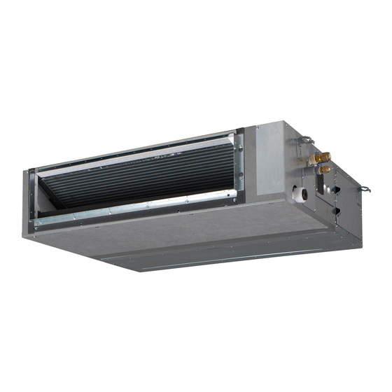
Daikin FBA35A2VEB Manual De Instalación
Ocultar thumbs
Ver también para FBA35A2VEB:
- Guía de referencia del instalador (24 páginas) ,
- Manual de instalación (20 páginas) ,
- Manual de instrucciones (20 páginas)
Tabla de contenido
Publicidad
Enlaces rápidos
Installation manual
Split system air conditioners
FBA35A2VEB
FBA50A2VEB
FBA60A2VEB
FBA71A2VEB
FBA100A2VEB
FBA125A2VEB
FBA140A2VEB
FBA35A2VEB9
FBA50A2VEB9
FBA60A2VEB9
FBA71A2VEB9
ADEA35A2VEB
ADEA50A2VEB
ADEA60A2VEB
ADEA71A2VEB
Installation manual
ADEA100A2VEB
English
Split system air conditioners
ADEA125A2VEB
Publicidad
Tabla de contenido

Resumen de contenidos para Daikin FBA35A2VEB
- Página 1 Installation manual Split system air conditioners FBA35A2VEB FBA50A2VEB FBA60A2VEB FBA71A2VEB FBA100A2VEB FBA125A2VEB FBA140A2VEB FBA35A2VEB9 FBA50A2VEB9 FBA60A2VEB9 FBA71A2VEB9 ADEA35A2VEB ADEA50A2VEB ADEA60A2VEB ADEA71A2VEB Installation manual ADEA100A2VEB English Split system air conditioners ADEA125A2VEB...
- Página 2 3P480520-4A...
- Página 3 3P480520-8B...
- Página 4 3P480520-11C...
-
Página 5: Tabla De Contenido
4.1.1 Installation site requirements of the indoor unit ..Daikin website (publicly accessible). 5 Installation ▪ The full set of latest technical data is available on the Daikin Mounting the indoor unit............extranet (authentication required). 5.1.1 Guidelines when installing the indoor unit.... -
Página 6: About The Units And Options
3 About the units and options About the units and options System layout ≥500 Service space Drain pipe Power supply wiring port Transmission wiring port Indoor unit Maintenance drain outlet Outdoor unit Gas pipe User interface Liquid pipe Suction air Discharge air ▪... -
Página 7: Installation
5 Installation Class f (mm) Installation 100~140 1460 Mounting the indoor unit Mounting the air inlet with a canvas connection Mounting the air inlet panel directly Ceiling surface 5.1.1 Guidelines when installing the indoor unit Ceiling opening Air inlet panel (optional accessory) INFORMATION Indoor unit (back side) Canvas connection for air inlet panel (optional accessory) -
Página 8: Guidelines When Installing The Ducting
5 Installation Nut (field supply) WARNING Double nut (field supply) Washer (accessories) Do NOT install operating ignition sources (example: open Hanger bracket (attached to the unit) flames, an operating gas appliance or an operating electric Indoor unit heater) in the duct work. Pipe Hanger bracket pitch (suspension) The ducting is to be field supplied. -
Página 9: To Check For Water Leaks
5 Installation ▪ Rising piping. If necessary to make the slope possible, you can install rising piping. ▪ Drain hose inclination: 0~75 mm to avoid stress on the piping and to avoid air bubbles. ▪ Rising piping: ≤300 mm from the unit, ≤625 mm perpendicular to the unit. -
Página 10: Connecting The Refrigerant Piping
5 Installation 1 2 3 5.2.1 To connect the refrigerant piping to the indoor unit CAUTION Install the refrigerating piping or components in a position P1 P2 F1 F2 T1 T2 where they are unlikely to be exposed to any substance which may corrode components containing refrigerant, unless the components are constructed of materials that are inherently resistant to corrosion or are suitably... -
Página 11: Connecting The Electrical Wiring
5 Installation 2 Check for leaks by applying the bubble test solution to all 3 Interconnection cable (indoor↔outdoor): Route the cable connections. through the frame, connect the cable to the terminal block (make sure the numbers match with the numbers on the 3 Discharge all nitrogen gas. -
Página 12: Configuration
6 Configuration Combination FBA35A FBA50A FBA60A FBA71A RZASG140M 4 (3.33) 3 (2.32) — 2 (2.05) RZQSG140L Combination FBA100A FBA125A FBA140A RZAG71M — — — 1 2 3 L N 1 2 3 L N 1 2 3 L N RZQG71L RZAG100M 1 (0.73) —... -
Página 13: Commissioning
7 Commissioning Setting content: Then Commissioning NOTICE Airflow adjustment is OFF 11(21) NEVER operate the unit without thermistors and/or Press ON/OFF to return to normal operating pressure sensors/switches. Burning of the compressor mode. might result. Possible consequence: The operation lamp will light up and the unit will start the fan operation for airflow automatic adjustment. -
Página 14: Error Codes When Performing A Test Run
▪ A subset of the latest technical data is available on the regional 4 Stop the test run. Daikin website (publicly accessible). ▪ The full set of latest technical data is available on the Daikin Action Result extranet (authentication required). -
Página 15: Wiring Diagram
9 Technical data Wiring diagram Unified Wiring Diagram Legend For applied parts and numbering, refer to the wiring diagram on the unit. Part numbering is by Arabic numbers in ascending order for each part and is represented in the overview below by symbol “*” in the part code. CIRCUIT BREAKER PROTECTIVE EARTH CONNECTION... - Página 16 4P456962-1D 2018.08...


