Publicidad
Idiomas disponibles
Idiomas disponibles
Enlaces rápidos
D512381, D514221
18 Gauge O-ring Repair Kit Instructions
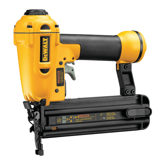
FOR USE WITH D51238 18 GA. 2" BRAD NAILER
FOR USE WITH D51422 18 GA. 1/4" NARROW CROWN
STAPLER
If you should have difficulty understanding the following
instructions contact a D
rized D
WALT service person.
E
Important Safety Instructions
• Read and understand tool instruction manual before attempting
repairs.
• Use only genuine D
WALT Replacement Parts.
E
• Always wear ANSI compliant eye protection.
• Disconnect air from tool and remove all nails before servicing.
• Always point tool in safe direction when reconnecting air
supply.
CAUTION:
• Do not allow dirt, dust or other foreign materials to enter the
tool.
• Be careful not to scratch or damage the o-rings or any internal
surfaces.
O-RING DESC.
# IN KIT PART #
O-Ring 37.1 x 2.05
O-Ring 31 x 2
O-Ring 25.7 x 3.5
O-Ring 36 x 2
Seal, Cylinder
Cap Gasket
Grease Tube
O-ring Reference Guide
PART #
398169-00
PART # 609020-00 (RED DOT)
1. Disconnect air from tool before
servicing or repairing.
2. Remove all nails from tool.
3. Remove four screws from top
cap (A) with 3 mm Allen wrench
provided in kit box.
4. Pull head valve (B), head valve
spring (C), and top bumper (D)
out of top cap through center of
head valve opening.
The following are trademarks for one or more D
on the handgrip; the kit box configuration; and the array of lozenge-shaped humps on the surface of the tool.
WALT service center or an autho-
E
REF. LETTER
1
609020-00
F
(Red Dot)
1
398169-00
E
1
398170-00
L
1
398171-00
M
1
395489-00
P
1
395488-00
O
1
606112-00
PART #
398170-00
PART # 398170-00
D
WALT Industrial Tool Co., 701 Joppa Road, Baltimore, MD 21286
E
(AUG06)
Form No. 644906-00
WALT power tools: the yellow and black color scheme; the "D" shaped air intake grill; the array of pyramids
E
5. Replace
(E – # 398169-00) and external
o-ring (F – # 609020-00/Red Dot)
on head valve.
6. Apply grease provided to o-rings in
head valve prior to assembly.
7. Remove cylinder hold down (G)
from tool.
8. Remove piston/driver subassembly
(H), cylinder (I), bumper (J) bumper
plate (N) and bulkhead (K) from tool.
I
M
G
K
9. Remove bulkhead (K) from cylinder.
10. Remove piston/driver subassembly (H) from cylinder.
11. Replace piston o-ring (L – # 398170-00) on driver blade/piston
assembly.
12. Replace check valve o-ring (M – # 398171-00) on cylinder.
13. Apply grease provided to all o-rings prior to assembly.
14. Ensure the inside of the tool is free from dirt and debris.
15. Place piston/driver subassembly
(H) back into cylinder (I).
16. Place bumper (J) onto bottom
of cylinder (I).
17. Place bumper plate (N) through
the piston/driver subassembly
(H) and onto the bottom of the
bumper (J).
18. D51238 ONLY
Making sure the piston/driver
subassembly's flat (smooth)
side is facing toward the FRONT of the tool, slide the cylinder/
bulkhead/piston/driver/bumper/bumper plate into the tool so
the piston/driver subassembly slides down the driver blade
channel in the nosepiece.
D51422 ONLY
Making sure the piston/driver subassembly's flat (smooth)
side is facing toward the BACK of the tool, slide the cylinder/
bulkhead/piston/driver/bumper/bumper plate into the tool so
the piston/driver subassembly slides down the driver blade
A
channel in the nosepiece.
19. Replace cylinder seal (P) with new one provided and snap onto
cylinder.
20. Replace cylinder hold-down (G) onto top of bulkhead (K).
21. Assemble top bumper into top cap (make sure it snaps into
place)
D512381, D514221
Copyright © 2006 D
B
internal
o-ring
J
H
K
WALT
E
B
O
C
D
E
F
RED DOT
L
P
H
I
J
N
Publicidad

Manuales relacionados para DeWalt D512381


Resumen de contenidos para DeWalt D512381
- Página 1 D512381, D514221 18 Gauge O-ring Repair Kit Instructions FOR USE WITH D51238 18 GA. 2" BRAD NAILER 5. Replace internal o-ring FOR USE WITH D51422 18 GA. 1/4" NARROW CROWN (E – # 398169-00) and external STAPLER o-ring (F – # 609020-00/Red Dot) If you should have difficulty understanding the following on head valve.
- Página 2 WALT service center. capuchon supérieur (A) avec la clé Allen de 3 mm fournie dans la trousse. D512381, D514221 4. Tirer sur la soupape principale (B) puis retirer le ressort (C) et la Directives pour la trousse de butée supérieure (D) du capuchon supérieur par le centre de remplacement des joints toriques pour l’ouverture de la soupape principale.
- Página 3 15. Remettre le sous-ensemble D512381, D514221 piston/extrémité motrice (H) Instrucciones del juego de reparación dans le cylindre (I). de juntas tóricas calibre 18 16. Mettre la butée (J) sur la partie inférieure du cylindre (I). PARA USAR CON LA CLAVADORA D51238 CALIBRE 18 17.
- Página 4 4. Tire de la válvula de suministro (B), el resorte de la válvula de el pistón/la defensa/paragolpe/la placa de la defensa/ suministro (C) y la defensa/paragolpe superior hacia afuera de paragolpe herramienta modo la tapa superior a través del centro de la abertura de la válvula subconjunto impulsor/pistón se deslice hacia abajo del de suministro.