Tabla de contenido
Publicidad
Idiomas disponibles
Idiomas disponibles
Enlaces rápidos
Publicidad
Capítulos
Tabla de contenido

Resumen de contenidos para Mobiclinic ATLAS
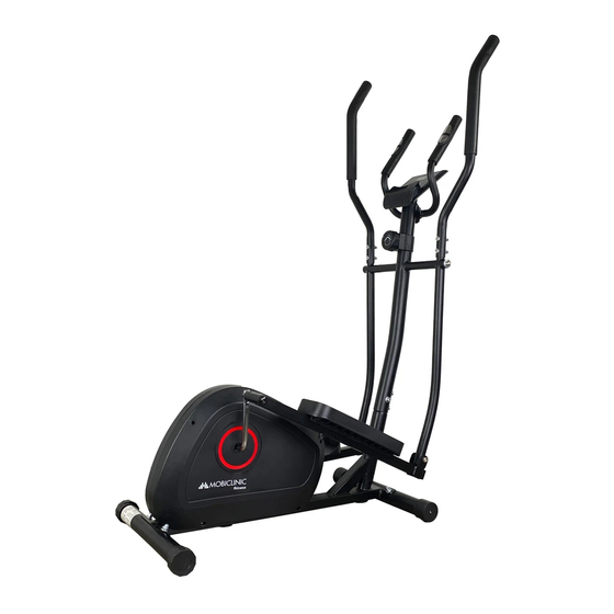
- Página 1 Manual de instrucciones Elíptica / Elliptical machine ATLAS Instrucciones en Español User manual in English Última revisión: 1 de Septiembre 2021 Guarde el manual para futuras consultas Last revision date: September 1st 2021 Safe this manual for future reference...
-
Página 2: Tabla De Contenido
ÍNDICE 1. Precauciones 2. Diagrama de piezas 3. Lista de piezas 4. Lista de componentes y piezas 4. Instrucciones de montaje 6. Funcionamiento del monitor 7. Solución de problemas 9. Recomendaciones - calentamiento y enfriamiento... -
Página 3: Precauciones
1. Precauciones Para reducir el riesgo de lesiones graves, lea todo el manual antes de ensamblar u operar la elíptica. En particu- lar, tenga en cuenta las siguientes precauciones de seguridad. 1. Es su responsabilidad asegurarse de que todos los usuarios del equipo estén infor- mados de todas las advertencias y precauciones. -
Página 4: Diagrama De Piezas
2. Diagrama de piezas... -
Página 5: Lista De Piezas
3. Lista de piezas Nº Nombre Nombre Nº Bastidor principal Arandela elástica 10MM Arandela de 10MM Estabilizador trasero Tapa trasera Tornillo carro M8*40 Estabilizador delantero Tornillo M8*15 Tapa frontal Tuerca abombada M8 Cable sensor inferior Arandela curva de 8MM Cable sensor superior Tornillo M8*60 Gancho tensión inferior 1/2 arandela... -
Página 6: Lista De Componentes Y Piezas
4 . Lista de componentes y piezas XR/L... -
Página 7: Instrucciones De Montaje
5 . Instrucciones de montaje Desembale la parte trasera y saque con cuidado las piezas. PASO 1 De acuerdo con el plano de piezas de la página 3, ensamble los dos estabilizadores traseros(2) y el bastidor principal (1) con la arandela curva de 8MM(7) del perno de carro M8*60 (8), luego apriételos con una llave. - Página 8 PASO 3 Utilice el tornillo M10*25 (27), la arandela elástica de 10MM (28), la arandela de 10MM (29), arandela "D" (51) y arandela ondulada (22) de 16MM para ensamblar el eje (31) y el poste (37), luego apriéte- los con la llave. Ensamble el tubo del pedal (20,21) y la manivela (12) con 1/2 perno del pedal (14R,14L), arandela ondulada de 16MM (22),...
- Página 9 PASO 5 Use X1 en el dibujo para ensam- blar la barra de la manija(25,26) y barra manija infe- rior(24,23) con tuerca abombada M8(6), arandela curva 8MM(7) y tornillo de carro M8*40(30), luego apriete con la llave. PASO 6 De acuerdo con el ejemplo de la figura, pase los tres cables de impulso de (50)a través del agu- jero...
-
Página 10: Funcionamiento Del Monitor
PASO 7 Conecte el cable de impul- sos (53) del ordenador (40) y el cable de impulsos (50) del manillar fijo (45). Coloque las pilas adecuadas en el estuche de las pilas. Monte el ordenador (40) y el poste delantero (37) con el tornillo M5*10(39) y el tapón final, luego apriételos con una llave. -
Página 11: Solución De Problemas
7. Solución de problemas 1. Cambio de la batería. Deslice el ordenador por el soporte, retire la tapa de la bate- ría en la parte posterior de la consola del ordenador y retire las baterías. Sustitúyalas por pilas AAA. Vuelva a colocar la tapa en la consola y deslice el ordenador de nuevo en el soporte. - Página 12 INDEX 1. Precautions 2. Parts diagram 3. Parts list 4. Components and parts list 4. Assembly instructions 6. Operation of the monitor 7. Problems solution 9. Recommendations - warm up and cool down...
-
Página 13: Precautions
1. Precautions To reduce the risk of serious injury, read the entire manual before assembling or operating the folding magne- tic exercise bike. In particular, observe the following safety precautions. 1. It is your responsibility to ensure that all users of the equipment are informed of all warnings and cautions. -
Página 14: Diagram Of Parts
2. Diagram of parts... -
Página 15: Parts List
3. Parts list nº Name Nº Name Main frame 10MM spring washer Rear stabilizer 10MM washer Rear end cap Carriage bolt M8*40 Front stabilizer axle Front end cap Screw M8*15 M8 domed nut Lower sensor wire 8MM curved washer Upper sensor wire Carriage bilt M8*60 Lower tension hook 1/2 washer... -
Página 16: Components And Parts List
4 . Components and parts list XR/L... - Página 17 5 . Assembly instructions Unpack the rear part and carefully remove the parts. STEP 1 According to the parts drawing on page 3, assemble the two rear stabili- zers(2) and the main frame (1) with the 8MM curved washer(7) of the M8*60 carriage bolt (8), then tighten them with a spanner.
- Página 18 STEP 3 Use the M10*25 bolt (27), 10MM spring washer (28), 10MM washer (29), "D" washer (51) and 16MM wave washer (22) to assemble the axle (31) and post (37), then tighten them with the spanner. Assemble pedal tube (20,21) and crank (12) with 1/2 pedal bolt (14) with 1/2 pedal bolt (14R,14L), 16MM wave washer (22), nylon...
- Página 19 STEP 5 Using X1 in the drawing to assem- ble the handle bar(25,26) and lower handle bar(24,23) with M8(6) countersunk nut, 8MM(7) curved washer and M8*40(30) carriage bolt, then tighten with spanner. STEP 6 According to the example in the figure, pass three...
-
Página 20: Operation Of The Monitor
STEP 7 Please connect the pulse wire (53) of computer(40) and pulse wire (50) of fixed handlebar(45). Put the right batteries into the battery case. Assemble the computer (40)and front post (37)with Screw M5*10 (39) and end plug,then tigh- ten them with a wrench. 6. -
Página 21: Problems Solution
7. Problems solution 1. Battery replacement. Slide the computer out of the cradle, remove the battery cover on the back of the computer console and remove the batteries. Replace them with AAA batteries. Replace the cover on the console and slide the computer back into the cradle.

