Publicidad
Idiomas disponibles
Idiomas disponibles
Enlaces rápidos
HARBOR BREEZE and logo design are
trademarks or registered trademarks of LF,
LLC. All rights reserved.
Serial Number
Purchase Date
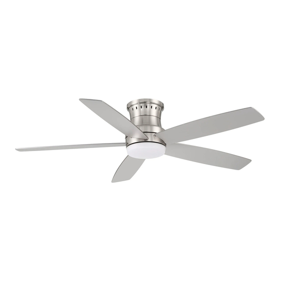
Thank you for purchasing this HARBOR BREEZE ceiling fan.
Questions, problems or missing parts?
Before returning, contact us on:
888-251-1003, 8 a.m. - 8 p.m., EST, Monday - Sunday or ascs@lowes.com.
SS23788
ITEM # 5660225 5660224 5660223 5660222
MODEL # AR24H-52BN AR24H-52BRZ AR24H-52MBK
AR24H-52MWH
DAMP CEILING FAN
1
LEWIND
Español p. 19
Publicidad

Manuales relacionados para Harbor Breeze AR24H-52BN


Resumen de contenidos para Harbor Breeze AR24H-52BN
- Página 1 Español p. 19 LLC. All rights reserved. Serial Number Purchase Date Thank you for purchasing this HARBOR BREEZE ceiling fan. Questions, problems or missing parts? Before returning, contact us on: 888-251-1003, 8 a.m. - 8 p.m., EST, Monday - Sunday or ascs@lowes.com.
- Página 2 TABLE OF CONTENTS Package Contents ..........................Hardware Contents ..........................Safety Information ..........................Preparation ............................Initial Installation ........................... Fan Installation ............................Wiring ..............................Final Installation ............................ Operating Instructions.......................... Operation............................... Care and Maintenance ........................Troubleshooting ............................ Limited Lifetime Warranty ........................Replacement Parts List ........................
- Página 3 PACKAGE CONTENTS PART DESCRIPTION QUANTITY PART DESCRIPTION QUANTITY Mounting Plate Fan motor Assembly Housing Ring Receiver + Remote Pack Blade Blade Support Plate (with Screws and Lock washers) IMPORTANT REMINDER: You must use the parts provided with this fan for proper installation and safety.
- Página 4 HARDWARE CONTENTS Wire Wire Qty. 4 (Remote Pack) Qty. 6 SAFETY INFORMATION Modifications not approved by the party responsible for compliance could void the user's authority to operate the equipment. *NOTE: This equipment has been tested and found to comply with the limits for a Class B digital device, pursuant to Part 15 of the FCC Rules.
- Página 5 SAFETY INFORMATION READ AND SAVE THESE INSTRUCTIONS Please read and understand this entire manual before attempting to assemble, install or operate the product. • Do not discard fan carton or foam inserts. Should this fan need to be returned to the factory for repairs, it must be shipped in its original packaging to ensure proper protection against damage that might exceed the initial cause for return.
- Página 6 SAFETY INFORMATION WARNING Risk of Fire and Electric Shock: Do not repair or service this light kit. The light source is designed for this specific application and can overheat if serviced by untrained personnel. If any servicing is required, call our customer service department (at 888-251-1003) for return authorization and shipping instructions.
- Página 7 INITIAL INSTALLATION 1. Turn off circuit breakers and wall switch to the fan supply line leads. DANGER: Failure to disconnect power supply prior to installation may result in serious injury or death. 2. This fan can be mounted as a flushmount on a regular (no-slope) ceiling only.
- Página 8 FAN INSTALLATION WARNING: To reduce the risk of fire, electric shock or other personal injury, mount the fan only to an outlet box or supporting Outlet Box system marked acceptable for fan support and use the mounting screws provided with the outlet box.
- Página 9 WIRING WARNING: Check to see that all connections Hardware Used are tight, including ground, and that no bare wire is Wire Nut visible at the wire nuts, except for the ground wire. CAUTION: Do not use with a wall light dimmer Wire Nut switch.
- Página 10 FINAL INSTALLATION Remove the fan motor assembly (E) from the mounting plate hook, and engage the key holes on the fan motor assembly (E) with the two mounting plate screws with lock washers previously loosened. Screws Install the two mounting plate screws with lock washers previously removed, and tighten all Grooves four mounting plate screws with lock washers.
- Página 11 FINAL INSTALLATION CAUTION: Before starting installation, Light Kit Mounting disconnect the power by turning off the circuit Plate breaker or removing the fuse at the fuse box. Turning power off using the fan switch is not sufficient to prevent electric shock. NOTE: If the light kit could be wobbled by hand, it means the light kit is not twisted completely till the right position.
- Página 12 OPERATING INSTRUCTIONS NOTE: The remote has been pre-paired in the factory for your convenience. NOTE: Batteries will weaken with age and should be replaced before leaking takes place as this Remote Control will damage the remote control. Dispose used batteries properly and keep them out of the reach of children.
- Página 13 OPERATING INSTRUCTIONS LEARNING PROCESS IMPORTANT: This fan has been pre-paired at the factory and the fan can be used now. If you have two or more fans, please follow steps below to control each fan independently. Also follow steps below to re-pair the remote and the LEARN receiver when needed.
- Página 14 OPERATING INSTRUCTIONS Power OFF: Press and release the power button to turn the fan off. 1, 2, 3 Speed functions 1 = Low speed 2 = Medium speed Remote 3 = High speed Control Light ON/OFF and Dimming Press and release the button to turn the light on or off.
- Página 15 OPERATION 1. The reverse switch is located on the surface of the motor housing. Slide the switch to the left for warm weather Reverse Switch operation. Slide the switch to the right for cool weather operation. NOTE: Wait for the fan to stop before reversing the direction of the blade rotation.
- Página 16 TROUBLESHOOTING WARNING: Before beginning work, shut off the power supply to avoid electrical shock. PROBLEM POSSIBLE CAUSE CORRECTIVE ACTION Fan does not move. 1. Reverse switch not engaged. 1. Push switch firmly either left or right. 2. Power is off or fuse is blown. 2.
- Página 17 LIMITED LIFETIME WARRANTY The distributor warrants this fan to be free from defects in workmanship and materials present at time of shipment from the factory for Lifetime limited from the date of purchase. This warranty applies only to the original purchaser. The distributor agrees to correct any defect at no charge or, at our option, replace the ceiling fan with a comparable or superior model.
- Página 18 REPLACEMENT PARTS LIST 888-251-1003, 8 a.m. - 8 p.m., EST, For replacement parts, call our customer service department at Monday - Sunday. You could also contact us at ascs@lowes.com. PART DESCRIPTION PARTS # 5660225-A 5660224-A 5660223-A Mounting Bracket 5660222-A 5660225-C 5660224-C 5660223-C Blade 5660222-C 5660225-C 5660224-C 5660223-C...
- Página 19 Número de serie Fecha de compra Gracias por comprar este ventilador de techo HARBOR BREEZE. ¿Preguntas, problemas o piezas faltantes? Antes de volver a la tienda, póngase en contacto: al teléfono 888-251-1003, de lunes a domingo, de 8 a.m. a 8 p.m., hora estándar del Este, o al correo electrónico ascs@lowes.com.
- Página 20 ÍNDICE Contenido del paquete.......................... Aditamentos ............................Información de seguridad........................Preparación............................Instalación inicial ..........................Instalación del ventilador........................Cableado.............................. Instalación final ............................ Instrucciones de funcionamiento......................Funcionamiento............................. Cuidado y mantenimiento........................Solución de problemas..........................Garantía limitada de por vida........................ Lista de piezas de repuesto........................
- Página 21 CONTENIDO DEL PAQUETE PIEZA DESCRIPCIÓN CANTIDAD PIEZA DESCRIPCIÓN CANTIDAD Placa de montaje Ensamble del motor del ventilador Anillo de la carcasa Aspa Placa de soporte del aspa Receptor + paquete del (con tornillos y arandelas control remoto de seguridad) RECORDATORIO IMPORTANTE: debe utilizar las piezas que se incluyen con este ventilador para la instalación adecuada y por seguridad.
- Página 22 ADITAMENTOS Empalme Empalme plástico plástico (paquete del Cant. 4 control remoto) Cant. 6 INFORMACIÓN DE SEGURIDAD Las modificaciones que no estén aprobadas por la parte responsable del cumplimiento podrían anular la autorización del usuario para utilizar el equipo. *NOTA: este equipo se probó y se verificó que cumple con los límites para un dispositivo digital de clase B, conforme a la sección 15 de las reglas de la FCC.
- Página 23 INFORMACIÓN DE SEGURIDAD LEA Y GUARDE ESTAS INSTRUCCIONES. Lea y comprenda completamente este manual antes de intentar ensamblar, instalar o usar el producto. • No deseche la caja del ventilador ni los accesorios de espuma. En caso de que deba devolverse este ventilador a la fábrica para realizarle reparaciones, debe enviarse en su empaque original para asegurar una protección adecuada contra daños que puedan agravar la causa inicial de la devolución.
- Página 24 INFORMACIÓN DE SEGURIDAD ADVERTENCIA Riesgo de incendio y descarga eléctrica: no repare ni realice mantenimiento a este kit de luces. La fuente de luz está diseñada para esta aplicación específica y puede sobrecalentarse si personal sin capacitación le realiza mantenimiento. Si requiere mantenimiento, llame a nuestro Departamento de Servicio al Cliente (al 888-251-1003) para enviarle una autorización de devolución y las instrucciones de envío.
- Página 25 INSTALACIÓN INICIAL 1. Interrumpa la línea de entrada del ventilador al apagar los interruptores de circuito y el interruptor de pared. PELIGRO: si no desconecta el suministro de electricidad antes de realizar la instalación, se pueden producir lesiones graves o la muerte.
- Página 26 INSTALACIÓN DEL VENTILADOR ADVERTENCIA: para reducir los riesgos de incendios, descargas eléctricas u otras lesiones personales, instale el ventilador solo Caja de salida en una caja de salida o en un sistema de soporte que estén marcados como aptos para sostener ventiladores y utilice los tornillos de montaje incluidos en la caja de salida.
- Página 27 CABLEADO ADVERTENCIA: verifique que todas las Aditamentos utilizados conexiones estén ajustadas, incluida la conexión a tierra, y que no haya conductores desnudos visibles Conector de cables en los empalmes plásticos, excepto el conductor con puesta a tierra. Conector de cables PRECAUCIÓN: no lo use con un regulador de intensidad de luz de pared.
- Página 28 INSTALACIÓN FINAL Retire el ensamble del motor del ventilador (E) del gancho de la placa de montaje y calce los orificios guía en el ensamble del motor del ventilador (E) con los dos tornillos de la placa de montaje y arandelas de seguridad que Tornillos aflojó...
- Página 29 INSTALACIÓN FINAL PRECAUCIÓN: antes de comenzar la Placa de montaje instalación, desconecte la alimentación colocando del kit de luces el interruptor de circuito en la posición de apagado o retirando el fusible de la caja de fusibles. No basta con colocar el interruptor del ventilador en la posición de apagado para evitar descargas eléctricas.
- Página 30 INSTRUCCIONES DE FUNCIONAMIENTO NOTA: el control remoto se ha emparejado previamente en la fábrica para su comodidad. NOTA: las baterías se debilitarán con el tiempo y deben reemplazarse antes de que se Control remoto produzcan fugas, ya que esto dañará el control remoto.
- Página 31 INSTRUCCIONES DE FUNCIONAMIENTO PROCESO DE APRENDIZAJE IMPORTANTE: este ventilador se emparejó previamente desde fábrica y se puede utilizar ahora. Si tiene dos o más ventiladores, siga los pasos que se presentan a continuación para controlar cada unidad de forma independiente. LEARN También siga los siguientes pasos para volver a emparejar el control remoto y el recibidor cada...
- Página 32 INSTRUCCIONES DE FUNCIONAMIENTO Apagado: presione y suelte el botón de encendido para apagar el ventilador. Funciones de velocidad 1, 2, 3 1 = Velocidad baja 2 = Velocidad media Control 3 = Velocidad alta remoto Encendido, apagado y atenuación de la luz Presione y suelte el botón para encender o apagar la luz.
- Página 33 FUNCIONAMIENTO 1. El interruptor de reversa está ubicado en la superficie de la carcasa del motor. Deslice el interruptor hacia la izquierda para que funcione Interruptor en climas cálidos. Deslice el interruptor hacia de reversa la derecha para que funcione en climas fríos. NOTA: espere a que el ventilador se detenga antes de invertir la dirección de rotación de las aspas.
- Página 34 SOLUCIÓN DE PROBLEMAS ADVERTENCIA: antes de comenzar cualquier trabajo, desconecte el suministro de electricidad para evitar descargas eléctricas. PROBLEMA CAUSA POSIBLE ACCIÓN CORRECTIVA El ventilador no se 1. El interruptor de reversa no está 1. Mueva firmemente el interruptor mueve. activado.
- Página 35 SOLUCIÓN DE PROBLEMAS PROBLEMA CAUSA POSIBLE ACCIÓN CORRECTIVA El ventilador funciona 1. Los conductores de la base no 1. Revise los cables de la base y, si es necesario, vuelva a conectarlos de pero la luz no. están bien conectados. acuerdo con las instrucciones de la 2.
- Página 36 LISTA DE PIEZAS DE REPUESTO Para obtener piezas de repuesto, llame a nuestro Departamento de Servicio al Cliente al 888-251-1003, de lunes a domingo, de 8 a.m. a 8 p.m., hora estándar del Este. También puede ponerse en contacto con nosotros a través de ascs@lowes.com. PIEZA DESCRIPCIÓN PIEZAS #...