Tabla de contenido
Publicidad
Idiomas disponibles
Idiomas disponibles
Enlaces rápidos
Publicidad
Tabla de contenido

Resumen de contenidos para Sapphire PC-AM2RD790
- Página 1 System Board User’s Manual 935-D790M1-120G S02700736E...
-
Página 2: Trademarks
Copyright This publication contains information that is protected by copyright. No part of it may be reproduced in any form or by any means or used to make any transfor- mation/adaptation without the prior written permission from the copyright hold- ers. -
Página 3: Tabla De Contenido
Table of Contents About this Manual................Warranty....................Static Electricity Precaution..............Safety Measures..................About the Package................Before Using the System Board............System Board Layout................English..................... Français....................Deutsch....................Español.................... -
Página 4: About This Manual
Introduction About this Manual An electronic file of this manual is included in the CD. To view the user’s manual in the CD, insert the CD into a CD-ROM drive. The autorun screen (Main Board Utility CD) will appear. Click the “TOOLS”... -
Página 5: Static Electricity Precaution
Introduction Static Electricity Precautions It is quite easy to inadvertently damage your PC, system board, components or devices even before installing them in your system unit. Static electrical discharge can damage computer components without causing any signs of physical damage. You must take extra care in handling them to ensure against electrostatic build-up. -
Página 6: About The Package
Introduction About the Package The system board package contains the following items. If any of these items are missing or damaged, please contact your dealer or sales representative for assistance. One system board One Bernstein audio module with cable One IDE round cable One floppy round cable Four Serial ATA data cables Four Serial ATA power cables... -
Página 7: System Board Layout
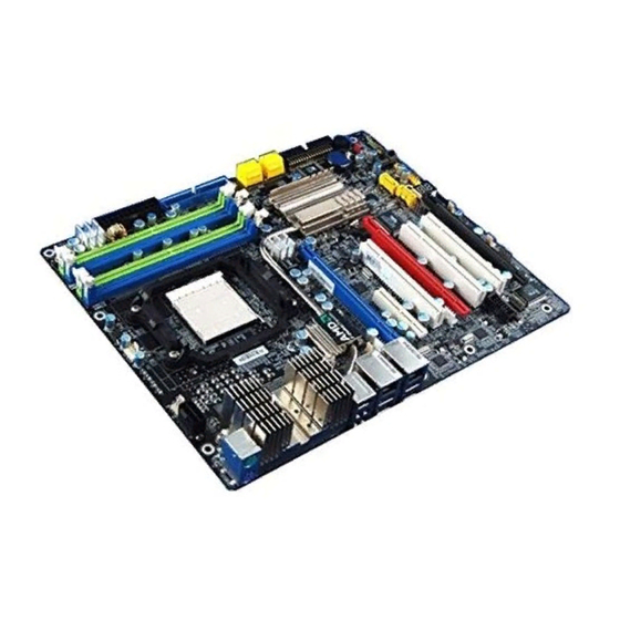
Introduction System Board Layout... -
Página 8: English
English Chapter 1 - Specifications Processor ® • AMD Phenom / Athlon 64 X2 / Athlon 64 FX / Athlon • Socket 940 AM2 65nm • HyperTransport 3.0 and 1.0 Chipset • AMD chipset - Northbridge: AMD 790FX - Southbridge: AMD SB600 System Memory •... - Página 9 English IEEE 1394 • VIA VT6307 • Supports two 100/200/400 Mb/sec ports Serial ATA with • AMD SB600 RAID - Supports up to 4 SATA devices - SATA speed up to 3Gb/s - RAID 0, RAID 1 and RAID 0+1 •...
-
Página 10: Jumper Settings
English Chapter 2 - Hardware Installation Jumper Settings Clear CMOS Data Clearing CMOS Data using JP2 1-2 On: Normal 2-3 On: (default) Clear CMOS Data If you encounter the following, a) CMOS data becomes corrupted. b) You forgot the supervisor or user password. c) The overclocked settings in the BIOS resulted to the system’s in- stability or caused system boot up problems. - Página 11 English ® Clearing CMOS Data using the EZ Clear Function ® EZ Clear bypasses the manual process of using a jumper to clear the CMOS by simply using the reset and power buttons. Important: ® EZ Clear is supported only if standby power is present in the system.
- Página 12 English PS/2 Power Select 1-2 On: 5V 2-3 On: (default) 5VSB Important: The 5VSB power source of your power supply must suppor t ≥720mA. Selecting 5VSB will allow you to use the PS/2 keyboard or PS/2 mouse to wake up the system. USB Power Select USB 0-5 (JP5)
- Página 13 English Speaker On/Off Select Buzzer 1-2 On: 2-3 On: Speaker Off Speaker On (default) The system board is equipped with a buzzer which serves as the PC’s speaker. By default the buzzer is “on” allowing you to hear the system’s beep messages and warnings. If you intend to use an exter- nal speaker, turn this function off by setting JP8 pins 1 and 2 to On.
- Página 14 English Rear Panel I/O Ports PS/2 LAN 1 LAN 2 Mouse 1394-0 USB 0-1 USB 4-5 PS/2 USB 2-3 PS/2 Ports and IEEE 1394 Ports PS/2 Mouse PS/2 KB 1394-0 1394-1 PS/2 Mouse and PS/2 Keyboard Ports These ports are used to connect a PS/2 mouse and a PS/2 key- board.
- Página 15 English USB Ports and LAN Ports USB 1 USB 0 LAN 1 USB 3 USB 2 LAN 2 USB 5 USB 4 USB 6-7 USB 8-9 USB Ports The USB ports are used to connect USB 2.0/1.1 devices. The 10-pin connectors allow you to connect 4 additional USB 2.0/1.1 ports.
- Página 16 English Bernstein Audio Module Audio Module Options CD-in CD-in Line-in Front Line-out Front audio audio Mic-in Optical Optical S/PDIF Center/ S/PDIF Subwoofer VoIP card Rear R/L connector Side R/L S/PDIF-out S/PDIF-in Bernstein Bernstein audio module audio module connector connector Side view Bernstein audio module Bernstein audio module using Realtek ALC888T...
- Página 17 English CD-in Connector The CD-in connector is used to receive audio from a CD-ROM drive, TV tuner or MPEG card. Front Audio Connector The front audio connector is used to connect to the line-out and mic-in jacks that are at the front panel of your system. Optical S/PDIF Connector The optical S/PDIF connector is used to connect an external audio output device using an optical S/PDIF cable.
- Página 18 English 3. The length of the audio cable provides the op- tion and flexibility of in- stalling the module on any available expansion bracket slot at the rear of the system chassis. Remove the screw of the bracket where you Audio cable want the audio module installed then remove the bracket.
- Página 19 English 3. Connect one end of the VoIP cable to the Bernstein audio mod- ule and the other end to the connector on the VoIP card. Connector on ALC888T Bernstein audio module Connector on VoIP card VoIP cable Side view VoIP card and cable properly connected...
- Página 20 English I/O Connectors Serial ATA Connectors SATA 1-2 SATA 1-4 supported by AMD SB600 SATA 3-4 SATA 6 SATA 5-6 supported by Silicon Image SiI3132 SATA 5 The Serial ATA (SATA) connectors are used to connect Serial ATA drives. Connect one end of the Serial ATA cable to the Serial ATA connector and the other end to your Serial ATA device.
- Página 21 English Floppy Disk Drive Connector and IDE Connector Floppy Disk Drive Connector The 90 floppy disk drive connector is used to connect a floppy drive. It has a keying mechanism to prevent improper floppy cable installation. Insert one end of the floppy cable into this connector and the other end-most connector to the floppy drive.
- Página 22 English IrDA, CIR and Serial (COM) Connectors IRRX Ground N. C. IRTX IrDA CIRTX 5VSB N. C. Ground CIRRX IrDA and CIR Connectors These connectors are used to connect an IrDA module and/or CIR module. Note: The sequence of the pin functions on some IrDA/CIR cable may be reversed from the pin function defined on the system board.
- Página 23 English Cooling Fan Connectors Sense Power Power Speed Ground N. C. Ground Control Fan 2 CPU fan On/Off Power Sense N. C. Ground Power 3rd fan NB fan N. C. Ground N. C. Ground Power Power 1st fan 2nd fan These fan connectors are used to connect cooling fans.
- Página 24 English LEDs DRAM Power LED Standby Diagnostic Power LED DRAM Power LED This LED will light when the system’s power is on. Standby Power LED This LED will light when the system is in the standby mode. Diagnostic LED The Diagnostic LED displays POST codes. POST (Power-On Self Tests) which is controlled by the BIOS is performed whenever you power-on the system.
-
Página 25: Power Connectors
English Power Connectors Use a power supply that complies with the ATX12V Power Supply Design Guide Version 1.1. An ATX12V power supply unit has a standard 24-pin ATX main power connector that must be inserted into this connector. 1 2 2 4 +3.3VDC +12VDC +5VDC... - Página 26 English The power connectors from the power supply unit are designed to fit the 24-pin and 8-pin connectors in only one orientation. Make sure to find the proper orientation before plugging the connectors. The FDD-type power connectors are additional power connector.s If you are using more than one graphics cards, we recommend that you plug power cables from your power supply unit onto the 5V/ 12V power connectors.
- Página 27 English Restarting the PC Normally, you can power-off the PC by: 1. Pressing the power button at the front panel of the chassis. 2. Pressing the power switch that is on the system board (note: not all system boards come with this switch). If for some reasons you need to totally cut off the power supplied to the PC, switch off the power supply or unplug the power cord.
- Página 28 English Front Panel Connectors RESET SPEAKER HD-LED PWR-LED ATX-SW HD-LED: Primary/Secondary IDE LED This LED will light when the hard drive is being accessed. RESET: Reset Switch This switch allows you to reboot without having to power off the system thus prolonging the life of the power supply or system. SPEAKER: Speaker Connector This connects to the speaker installed in the system chassis.
- Página 29 English PWR-LED: Power/Standby LED When the system’s power is on, this LED will light. When the system is in the S1 (POS - Power On Suspend) or S3 (STR - Suspend To RAM) state, it will blink every second. Note: If a system did not boot-up and the Power/Standby LED did not light after it was powered-on, it may indicate that the CPU or memory module was not installed properly.
- Página 30 English PCI Express Slots PCI Express x16 PCI Express x4 PCI Express x16 PCI Express x16 PCI Express x16 Install PCI Express x16 graphics card, that comply to the PCI Ex- press specifications, into the PCI Express x16 slot. To install a graph- ics card into the x16 slot, align the graphics card above the slot then press it down firmly until it is completely seated in the slot.
- Página 31 English Chapter 3 - RAID The AMD SB600 chip alows configuring RAID on 4 Serial ATA drives. It supports RAID 0, RAID 1 and RAID 0+1. The Silicon Image Sil3132 chip allows configuring RAID on another 2 Serial ATA drives. It supports RAID 0, RAID 1 and RAID 0+1. RAID Levels RAID 0 (Striped Disk Array without Fault Tolerance) RAID 0 uses two new identical hard disk drives to read and write...
- Página 32 English Step 1: Connect the Serial ATA Drives Refer to chapter 2 for details on connecting the Serial ATA drives. Important: Make sure you have installed the Serial ATA drives and connected the data cables otherwise you won’t be able to enter the RAID BIOS utility. Treat the cables with extreme caution especially while creating RAID.
- Página 33 English Step 4: Install the RAID Driver During OS Installation ® The RAID driver must be installed during the Windows XP or ® Windows 2000 installation using the F6 installation method. This is required in order to install the operating system onto a hard drive or RAID volume when in RAID mode or onto a hard drive when in AHCI mode.
-
Página 34: Français
Français Chapitre 1 - Spécifications Processeur ® • AMD Phenom / Athlon 64 X2 / Athlon 64 FX / Athlon • Socket 940 AM2 65nm • HyperTransport 3.0 et 1.0 Chipset • AMD chipset ® - Pont nord: AMD 790FX - Pont sud: AMD SB600 Mémoire Système •... - Página 35 Français IEEE 1394 • VIA VT6307 • Supporte 2 100/200/400 Mb/sec ports Serial ATA avec • AMD SB600 RAID - 4 dispositifs de SATA - SATA allant jusqu’à 3Gb/s - RAID 0, RAID 1 et RAID 0+1 • Silicon Image Sil3132 - 2 dispositifs de SATA - SATA allant jusqu’à...
- Página 36 Français Chapitre 2 - Installation de Matériel Cavalier Effacer les Données CMOS Effacement des Données CMOS en Utilisant JP2 1-2 On: Normal 2-3 On: Effacer les données (défaut) CMOS Si vous rencontrez les éléments suivants, a) Données CMOS devenant corrompues b) Vous avez oublié...
-
Página 37: Important
Français ® Effacement des Données CMOS en Utilisant la Fonctionnalité EZ Clear ® EZ Clear contourne le processus manuel d’utilisation d’un cavalier pour effacer CMOS en utilisant simplement les boutons de réinitialisation et d’alimentation. Important: EZ Clear ® n’est supportée que si l’alimentation de veille est présente sur le système. - Página 38 Français Sélectionner l’alimentation PS/2 1-2 On: 5V 2-3 On: (défaut) 5VSB Important: La source d’alimentation 5VSB de votre alimentation doit suppor tée ≥720mA. En sélectionnant 5VSB, vous pourrez utiliser le clavier PS/2 ou la souris PS/2 pour “réveiller” le système. Sélectionner l’alimentation USB USB 0-5 (JP5)
- Página 39 Français Sélection des Haut-parleurs ON/OFF Avertisseur sonore 2-3 On: 1-2 On: Haut-parleurs Haut-parleurs ON (défaut) La carte système est équipée d’un avertisseur sonore qui sert en tant que haut-parleur du PC. Par défaut l’avertisseur sonore est « ON » permettant d’entendre les « bips » des messages et les aver tissements.
- Página 40 Français Ports I/O de l’arrière du Panneau PS/2 LAN 1 LAN 2 Mouse 1394-0 USB 0-1 USB 4-5 PS/2 USB 2-3 Ports PS/2 et IEEE 1394 PS/2 Mouse PS/2 KB 1394-0 1394-1 Ports Souris PS/2 et Clavier PS/2 Ces ports sont utilisés pour raccorder une souris PS/2 et un clavier PS/2.
- Página 41 Français Ports USB et LAN USB 1 USB 0 LAN 1 USB 3 USB 2 LAN 2 USB 5 USB 4 USB 6-7 USB 8-9 Ports USB Les ports USB sont utilisés pour raccorder des appareils USB 2.0/ 1.1. Les connecteurs 10 broches vous permettent de raccorder 4 autres ports USB 2.0/1.1.
- Página 42 Français Module Audio Bernstein Options Module Audio CD-in CD-in Line-in Front Front Line-out audio audio Mic-in Optical Optical S/PDIF Center/ S/PDIF Subwoofer Connecteur Rear R/L de carte VoIP Side R/L S/PDIF-out S/PDIF-in Connecteur Connecteur module Audio module Audio Bernstein vue latérale Bernstein Module audio Bernstein Module audio Bernstein...
- Página 43 Français Prises coaxiales d’entrée RCA S/PDIF et de sortie SPDIF Ces prises sont utilisées pour connecter les appareils de sortie audio externes en utilisant les câbles coaxiaux S/PDIF. Connecteur d’entrée CD Le connecteur d’entrée CD est utilisé pour recevoir les signaux audio d’un lecteur CD-ROM, d’une carte TV ou MPEG.
- Página 44 Français 2 Insérer une extrémité du câble sur le connecteur Audio Bernstein sur la car te système et l’autre connecteur correspondant sur le mod- ule audio. Connecteur module Audio Bernstein 3. La longueur du câble audio donne la possibilité d’installer le module sur toute fente d’extension disponible à...
- Página 45 Français Installation de la carte VoIP (optionnel) 1. Le câble inclus dans le kit VoIP est utilisé pour raccorder la carte VoIP Câble VoIP module audio Bernstein. carte VoIP 2. Installer la car te VoIP dans fente d’extension disponible - à...
- Página 46 Français Connecteur sur la carte VoIP Câble VoIP vue latérale Carte VoIP et câble correctement raccordés.
- Página 47 Français Connecteurs I/O Les Connecteurs en Série ATA SATA 1-4 est SATA 1-2 suppor té par AMD SATA 3-4 SB600 SATA 6 SATA 5-6 est supporté par Silicon Image SiI3132 SATA 5 Les connecteurs en série ATA (SATA) sont utilisés pour raccorder les disques durs ATA en série.
- Página 48 Français Connecteur de Lecteur de Disquettes et Connecteur IDE Connecteur de Lecteur de Disquettes Le connecteur de lecteur de disquettes 90° est utilisé pour raccorder le lecteur de disquettes. Il possède un mécanisme d’insertion qui empêche sa mauvaise installation. Insérer une extrémité du câble du lecteur de disquette dans ce connecteur et l’autre dans le lecteur de disquette.
- Página 49 Français Connecteurs IrDA, CIR et en Série (COM) IRRX Ground N. C. IRTX IrDA CIRTX 5VSB N. C. Ground CIRRX Connecteurs IrDA et CIR .Ces connecteurs sont utilisés pour raccorder le module IrDA ou/et le module CIR. Note: La séquence de la fonction des broches (signal) sur certains câbles IrDA/CIR peut être inversée à...
- Página 50 Français fente disponible à l’arrière du châssis du système et raccorder le câble du port en série à ce connecteur. Le bord coloré du câble devrait être aligné avec l’ergot 1 de ce connecteur. Connecteurs de Ventilateur de Refroidissement Sense Power Power Speed...
- Página 51 Français Commutateurs à Touche EZ Réinitialisation Alimentation La présence des commutateurs d’alimentation et de réinitialisation sur la carte système est conviviale et particulièrement pour les utilisateurs étant bricoleurs. Ils sont très pratiques pour allumer ou réinitialiser le système tout en ajustant la car te système avant l’installation sur le châssis.
- Página 52 Français Voyants DEL Voyant d’alimentation DRAM Voyant DEL Voyant DEL d’alimentation à de diagnostic l’état de veille Voyant DEL d’alimentation DRAM Ce voyant DEL s’allumera lorsque le système est allumé. Voyant DEL d’alimentation à l’état de Veille Ce voyant DEL s’allumera lorsque le système est en mode veille. Voyant DEL de Diagnostic Le voyant DEL de diagnostic affiche les codes POST.
-
Página 53: Connecteurs D'alimentation
Français Connecteurs d’alimentation Utiliser une alimentation électrique conforme à la version 1.1 du guide d’alimentation électrique ATX12V. Une unité d’alimentation électrique ATX12V possède un connecteur d’alimentation principale ATX à 24 broches qui doit être inséré dans ce connecteur. 1 2 2 4 +3.3VDC +12VDC +5VDC... - Página 54 Français Les connecteurs d’alimentation de l’unité d’alimentation électrique sont conçus pour s’adapter aux connecteurs à 24 et 8 broches seulement dans une direction. S’assurer d’observer la bonne orienta- tion avant de brancher les connecteurs. Les connecteurs d’alimentation de type FDD sont des connecteurs supplémentaires d’alimentation.
- Página 55 Français Redémarrage du PC Normalement vous pouvez éteindre le PC en : 1. Appuyant sur le bouton d’alimentation sur le panneau frontal du chassis. 2. En appuyant sur le commutateur d’alimentation se trouvant sur la carte système (note : toutes les cartes systèmes ne possèdent pas ce commutateur) Si, pour quelque raison que ce soit, vous devez éteindre l’alimentation du PC, éteindre l’alimentation ou débrancher le cordon d’alimentation.
- Página 56 Français Connecteurs Frontaux du Panneau RESET SPEAKER HD-LED PWR-LED ATX-SW HD-LED: Voyant DEL IDE Principal/Secondaire Ce voyant DEL s’allumera lorsqu’on accède au disque dur. RESET: Commutateur de Réinitialisation Ce commutateur vous permet de redémarrer sans avoir à éteindre le système et par conséquent en permettant une durée de vie de l’alimentation ou du système prolongée.
- Página 57 Français PWR-LED: Voyant DEL d’alimentation / état de veille Ce voyant DEL s’allumera lorsque le système est allumé. Lorsque le système est sur le statut S1 (POS – alimentation suspendue) ou S3 (STR – suspendue dans la RAM), il clignotera toutes les secondes. Note: Si le système n’a pas démarré...
- Página 58 Français Fentes PCI Express PCI Express x16 PCI Express x4 PCI Express x16 PCI Express x16 PCI Express x16 Installer la carte graphique PCI Express X 16 se conformant aux spécifications PCI Express dans la fente X 16 du PCI Express. Pour installer une carte graphique dans la fente x16, aligner la car te graphique au-dessus de la fente et appuyer vers le bas fermement jusqu’à...
- Página 59 Français Chapitre 3 - RAID La puce AMD SB600 permet la configuration du système RAID sur 4 disques durs ATA. Elle supporte les systèmes RAID 0, RAID 1 et RAID 0+1. La puce Silicon Image Sil3132 permet la configuration du système RAID sur 2 autres disques durs en série ATA.
- Página 60 Français Réglages Pour activer la fonctionnalité RAID, les réglages suivants sont nécessaires: 1. Raccorder les disques durs en série ATA. 2. Configurer le disque ATA en série dans le BIOS. 3. Configurer les systèmes RAID dans le BIOS RAID. 4. Installer le driver RAID lors de l’installation du SE (système ion.
- Página 61 Français la touche <F4> pour entrer dans l’utilitaire. L’utilitaire vous permet de créer un système RAID sur des disques durs en série ATA. Configurer le système RAID dans le BIOS Sil3132 Sata RAID. Lorsque le système démarre et que tous les disques durs ont été détectés, le message de statut BIOS Silicon Image apparaîtra.
-
Página 62: Deutsch
Deutsch Kapitel 1 - Spezifikation ® Prozessor • AMD Phenom / Athlon 64 X2 / Athlon 64 FX / Athlon • Socket 940 AM2 65nm • HyperTransport 3.0 und 1.0 Chipset • AMD chipset ® - Nordbrücke: AMD 790FX - Südbrücke: AMD SB600 Systemspeicher •... - Página 63 Deutsch IEEE 1394 • VIA VT6307 • Unterstützt 2 100/200/400 Mb/sec porte Serial ATA mit RAID • AMD SB600 - 4 SATA-Vorrichtungen - SATA bis zu 3Gb/s schnell - RAID 0, RAID 1 und RAID 0+1 • Silicon Image Sil 3132 - 2 SATA-Vorrichtungen - SATA bis zu 3Gb/s schnell - RAID 0, RAID 1 und RAID 0+1...
- Página 64 Deutsch Kapitel 2 - Installieren des Hardware Jumper Löschen der CMOS Daten Löschen der CMOS Daten unter Verwendung von JP2 1-2 On: Normal 2-3 On: Lösche (Standardwer t) CMOS Daten Sollten Sie eins der folgenden Probleme haben, a) die CMOS Daten sind beschädigt. b) Sie haben das Supervisor oder User Passwort vergessen.
- Página 65 Deutsch 3. Verbinden Sie nun wieder den Netzstecker und schalten Sie das System ein. ® Löschen der CMOS Daten unter Verwendung der EZ Clear Funktion ® EZ Clear umgeht den manuellen Prozess des Setzens der Jumper zum Löschen des CMOS durch einfache Betätigung der Reset- und Power-Schalter.
- Página 66 Deutsch PS/2 Power Select 1-2 On: 5V 2-3 On: (Standard) 5VSB Wichtig: 5VSB Stromquelle Ihres Netzteils muss ≥720mA unterstützen. Die Auswahl von 5VSB erlaubt es Ihnen, Ihr System per PS/2 Key- board oder PS/2 Maus aufzuwecken. USB Power Select USB 0-5 (JP5) 1-2 On: 5V 2-3 On:...
- Página 67 Deutsch Speaker On/Off Auswahl Summer 1-2 On: 2-3 On: Speaker Off Speaker On (Standard) Das Systemboard ist mit einem Summer ausgestattet, der als Lautsprecher des PC’s dient. Ab Werk ist die Standardeinstellung des Summers “on” wodurch Sie die Warnungen und Piep-Nachrichten des Systems hören.
- Página 68 Deutsch Rückseite I/O Ports PS/2 LAN 1 LAN 2 Mouse 1394-0 USB 0-1 USB 4-5 PS/2 USB 2-3 PS/2 Ports und IEEE 1394 Ports PS/2 Mouse PS/2 KB 1394-0 1394-1 PS/2 Maus und PS/2 Keyboard Ports Diese Ports werden zum Anschluss von PS/2 Maus und PS/2 Key- board verwendet.
- Página 69 Deutsch USB Ports und LAN Ports USB 1 USB 0 LAN 1 USB 3 USB 2 LAN 2 USB 5 USB 4 USB 6-7 USB 8-9 USB Ports Über die USB Ports verbinden Sie USB 2.0/1.1 Geräte. Die 10-Pin Anschlüsse erlauben Ihnen den Anschluss von 4 zusätzlichen USB 2.0/1.1 Ports.
- Página 70 Deutsch Bernstein Audio-Modul Audio-Modul Optionen CD-in CD-in Line-in Front Line-out Front audio audio Mic-in Optischer Optischer S/PDIF Center/ S/PDIF Subwoofer Rear R/L Anschluss für eine VoIP- Side R/L Karte S/PDIF-out S/PDIF-in Bernstein Bernstein audio module audio module Anschluss Anschluss Side view Bernstein Audio-Modul Bernstein Audio-Modul mit Realtek ALC885...
- Página 71 Deutsch Coaxial RCA S/PDIF-in und SPDIF-out Stecker Mit diesen Steckern verbinden Sie externe Audioausgabegeräte die koaxiale S/PDIF Kabel verwenden. CD-in Anschluss Der CD-in Anschluss wird verwendet, um Audio von einem CD- ROM Laufwerk, einer TV Tuner oder MPEG-Karte zu empfangen. Front Audio Anschluss Mit dem Front Audio Anschluss werden die line-out und mic-in Stecker die sich an der Frontseite des Gehäuses befinden verbunden.
- Página 72 Deutsch 2. Verbinden Sie das eine Ende des Audiokabels mit dem Bernstein Audioanschluss auf dem Systemboard und das andere Ende entsprechenden Anschluss auf dem Audiomodul. Bernstein audio module connector 3. Die Länge des Audiokabels bietet Ihnen die Option und Flexibilität, das Modul in jede beliebige Halterung auf der Rückseite des Gehäuses einzusetzen.
- Página 73 Deutsch Installation der VoIP-Karte (zur option) 1. Das im Lieferumfang der VoIP-Kar te enthaltene Kabel dient dazu, die VoIP-Kabel VoIP-Kar te mit dem Bernstein Audio-Modul zu verbinden. VoIP-Karte 2. Installieren Sie die VoIP- Kar te einen v e r f ü g b a r e n Erweiterungssteckplatz –...
- Página 74 Deutsch Anschluss an der VoIP-Karte VoIP -Kabel Seitenansicht Korrekt angeschlossene VoIP-Karte und Kabel...
- Página 75 Deutsch I/O Anschlüsse Serial ATA Anschlüsse SATA 1-2 SATA 1-4 unterstützt durch AMD SB600 SATA 3-4 SATA 6 SATA 5-6 unterstützt durch Silicon Image SiI3132 SATA 5 Über die Serial ATA (SATA) Anschlüsse werden Serial ATA Laufwerke angeschlossen. Verbinden Sie das eine Ende des Serial ATA Kabels mit dem Serial ATA Anschluss und das andere Ende mit Ihrem Serial ATA Gerät.
- Página 76 Deutsch Floppy Disk Drive Anschluss und IDE Anschluss Floppy Disk Drive Anschluss Über den 90 Floppy Disk Drive Anschluss werden Floppy- Laufwer ke angeschlossen. verfügt über einen Verbindungsmechanismus der eine Fehlinstallation vermeidet. Verbinden Sie ein Ende des Floppy-Kabels mit dem Anschluss auf dem Board und das andere Ende mit dem Floppy-Laufwerk.
- Página 77 Deutsch IrDA, CIR und Serial (COM) Anschlüsse IRRX Ground N. C. IRTX IrDA CIRTX 5VSB N. C. Ground CIRRX IrDA und CIR Anschlüsse Über diese Anschlüsse werden IrDA Module und/oder CIR Module angeschlossen. Bitte beachten: Die Anordnung der PIN-Funktionen kann bei einigen IrDA/CIR Kabeln abweichend von der Anordnung auf dem Systemboard sein.
- Página 78 Deutsch Ports mit dem entsprechenden Anschluss. Das farblich markier te Ende des Kabels muss mit Pin 1 des Anschlusses in Übereinstimmung gebracht werden. Lüfteranschlüsse Sense Power Power Speed Ground N. C. Ground Control Fan 2 CPU fan On/Off Power Sense N.
- Página 79 Deutsch EZ Touch Schalter Reset Power Das Vorhandensein von Power- und Reset-Schaltern auf dem Systemboard ist speziell für DIY-User sehr anwenderfreundlich. Sie bieten die Möglichkeit bequem das System ein-/auszuschalten und einen Reset durchzuführen und somit die Einstellungen des Systemboards zu verfeinern bevor es in ein Gehäuse eingebaut wird.
- Página 80 Deutsch LEDs DRAM Power LED Standby Diagnostic Power LED DRAM Power LED Diese LED leuchtet wenn das System eingeschaltet ist. Standby Power LED Diese LED leuchtet wenn das System im Standby Modus ist. Diagnostic LED Die Diagnostic LED zeigt POST Codes an. POST (Power-On Self Tests), die durch das BIOS gesteuert werden, werden bei jedem Start des Systems durchgeführt.
- Página 81 Deutsch Stromanschlüsse Verwenden Sie ein Netzteil, dass den ATX12V Netzteil Designrichtlinien Version 1.1 entspricht. Ein ATX12V Netzteil verfügt über einen standard 24-Pin ATX Hauptstromanschluss. Verbinden Sie diese Stromanschlüsse. 1 2 2 4 +3.3VDC +12VDC +5VDC +12VDC +5VDC +5VDC +5VSB PWR_OK +5VDC PS_ON# +5VDC...
- Página 82 Deutsch Die Stromanschlüsse des Netzteils sind so entworfen, dass die die 24-Pin und 8-Pin Anschlüsse nur in einer Ausrichtung verbunden werden können. Stellen Sie sicher, dass die Ausrichtung korrekt ist bevor Sie die Anschlüsse verbinden. Die FDD-Typ Stromanschlüsse sind zusätzliche Stromanschlüsse. Sollten Sie mehr als eine Grafikkarte verwenden, so empfehlen wir, dass Sie die Stromkabel des Netzteils mit den 5V/12V Stromanschlüssen verbinden.
- Página 83 Deutsch Neustart des PC’s In der Regel lässt sich der PC wie folgt ausschalten: 1. Betätigung des Power-Schalters auf der Frontseite des Gehäuses. oder 2. Betätigung des Power-Schalters der sich auf dem Systemboard befindet (Anmerkung: nicht alle Systemboards verfügen über diesen Schalter).
- Página 84 Deutsch Frontanschlüsse RESET SPEAKER HD-LED PWR-LED ATX-SW HD-LED: Primäre/Sekundäre IDE LED Diese LED leuchtet auf, wenn auf die Festplatte zugegriffen wird. RESET: Reset-Schalter Dieser Schalter erlaubt es Ihnen einen Neustart durchzuführen ohne die Stromzufuhr zu unterbrechen. Dadurch wird die Lebensdauer des Netzteils und des Systems verlängert.
- Página 85 Deutsch PWR-LED: Power/Standby LED Diese LED leuchtet, wenn die Stromzufuhr des Systems eingeschaltet ist. Sollte das System sich im S1 (POS - Power On Suspend) oder S3 (STR - Suspend To RAM) Status befinden, so blinkt die LED einmal pro Sekunde. Bitte beachten: Sollte das System nicht hochfahren und die Power/Standby LED nicht aufleuchten nachdem Sie den Power-Schalter betätigt...
- Página 86 Deutsch PCI Express Steckplätze PCI Express x16 PCI Express x4 PCI Express x16 PCI Express x16 PCI Express x16 Installieren Sie eine PCI Express x16 Grafikkarte, die den PCI Express Spezifikationen entspricht in den PCI Express x16 Steckplatz. Zur Instal- lation der Grafikkarte in den x16 Steckplatz richten Sie die Grafikkarte über dem Steckplatz aus und drücken sie dann in den Steckplatz bis sie fest sitzt.
- Página 87 Deutsch Kapitel 3 - RAID Der AMD SB600 Chip er laubt es RAID auf 4 Serial ATA Festplatten zu konfigurieren. Er unterstützt RAID 0, RAID 1 und RAID 0+1. Der Silicon Image Sil3132 Chip erlaubt es RAID auf 2 weiteren Serial ATA Festplatten zu konfigurieren.
- Página 88 Deutsch Einstellungen Um die RAID-Funktion zu aktivieren sind folgende Einstellungen notwendig. 1. Schliessen Sie die Serial ATA Laufwerke an. 2. Konfigurieren Sie Serial ATA im Award BIOS. 3. Konfigurieren Sie RAID im RAID BIOS. 4. Installieren Sie den RAID-Treiber während der Installation des Betriebssystems.
- Página 89 Deutsch Drücken Sie die <F4> Taste um das Programm aufzurufen. Das Programm ermöglicht es Ihnen ein RAID system auf den Serial ATA Laufwerken einzurichten. Konfiguration von RAID im Sil3132 SataRAID BIOS Wenn das System hochfährt und alle Laufwerke erkannt wurden erscheint die Silicon Image BIOS Status Nachricht auf dem Bildschirm.
-
Página 90: Español
Español Chapter 1 - Especificaciones ® Procesador • AMD Phenom / Athlon 64 X2 / Athlon 64 FX / Athlon • Socket 940 AM2 65nm • HyperTransport 3.0 y 1.0 Chipset • AMD chipset ® - Puente norte: AMD 790FX - Puente sur: AMD SB600 Memoria de Sistema •... - Página 91 Español •Soporta las unidades duras hasta de UltraDMA 133Mbps IEEE 1394 • VIA VT6307 • Sopor ta 2 ports 100/200/400 Mb/sec Dispositivo de • AMD SB600 Almacenaje - 4 dispositivo de Serial ATA - Velocidad SATA de hasta 3Gb/s - RAID 0, RAID 1 y RAID 0+1 •...
-
Página 92: Borrar Datos Cmos
Español Chapter 2 - Instalación del Hardware Puente Borrar Datos CMOS Borrar Datos CMOS Usando JP2 1-2 On 2-3 On (encendido): (encendido): Normal Borrar datos (predeterminado) CMOS En alguno de los siguientes casos, a) los datos CMOS se corrompen. b) ha olvidado la contraseña del supervisor o del usuario. c) La configuración de overlock en el BIOS causó... - Página 93 Español ® Borrar Datos de CMOS Mediante la Función EZ Clear ® EZ Clear pasa por alto el proceso manual que utiliza un puente de conexión para borrar el CMOS al utilizar sólo los botones reset (reinicio) y power (encendido). Importante: ®...
-
Página 94: Selector De Alimentación Usb
Español Selector de Alimentación PS/2 1-2 On: 5V 2-3 On: (default) 5VSB Importante: La fuente de alimentación 5VSB de suministro eléctrico debe admitir ≥720mA. Seleccionar 5VSB le permitirá utilizar el teclado PS/2 o el ratón PS/2 para despertar el sistema. Selector de Alimentación USB USB 0-5 (JP5) -
Página 95: Selector De Encendido/Apagado De Altavoz
Español Selector de Encendido/Apagado de Altavoz Zumbador 1-2 On 2-3 On (encendido): (encendido): Altavoz Altavoz encendido apagado (predeterminado) La placa del sistema cuenta con un zumbador que sirve como altavoz del PC. Por defecto, el zumbador se encuentra encendido, lo que le permite escuchar los mensajes y advertencias del sistema. -
Página 96: Puertos I/O Del Panel Posterior
Español Puertos I/O del Panel Posterior PS/2 LAN 1 LAN 2 Mouse 1394-0 USB 0-1 USB 4-5 PS/2 USB 2-3 Puertos PS/2 y Puertos IEEE 1394 PS/2 Mouse PS/2 KB 1394-0 1394-1 Puertos para Ratón PS/2 y Teclado PS/2 Estos puertos se utilizan para conectar un ratón PS/2 y un teclado PS/2. -
Página 97: Puertos Usb Y Puertos Lan
Español Puertos USB y Puertos LAN USB 1 USB 0 LAN 1 USB 3 USB 2 LAN 2 USB 5 USB 4 USB 6-7 USB 8-9 Puertos USB Los puertos USB se utilizan para conectar dispositivos USB 2.0/1.1 El conector de 10 pines permite conectar 4 puertos USB 2.0/1.1 adicionales. -
Página 98: Módulo De Audio Bernstein
Español Módulo de Audio Bernstein Opciones del Módulo de Audio CD-in CD-in Line-in Front Line-out Front audio audio Mic-in Optical Optical S/PDIF Center/ S/PDIF Subwoofer Conector Rear R/L tarjeta VoIP Side R/L S/PDIF-out S/PDIF-in conector de conector de Bernstein Bernstein audio module audio module Visión Lateral... -
Página 99: Instalación Del Módulo De Audio Bernstein
Español Enchufes coaxiales RCA S/PDIF de entrada (S/PDIF-In) y SPDIF de salida (S/PDIF-Out) Estos enchufes se utilizan para conectar dispositivos de salida de audio externos mediante cables coaxiales S/PDIF. Conector de entrada de CD (CD-In) El conector de entrada de CD se utiliza para recibir audio de un lector de CD-ROM, de un sintonizador de TV o de una placa MPEG. - Página 100 Español 2. Inserte un extremo del cable en el conector de audio Bernstein de la placa del sistema y el otro extremo en el conector correspondiente del módulo de audio. Bernstein audio module connector 3. El largo del cable de audio brinda la posibilidad y flexibilidad de instalar el módulo en cualquier ranura...
- Página 101 Español Instalar la tarjeta VoIP (opcional) 1. El cable proporcionado en el estuche VoIP se utiliza para conectar la Cable VoIP tarjeta VoIP al módulo de audio Bernstein. tarjeta VoIP 2. Instale la tarjeta VoIP en una ranura de expansión disponible –...
- Página 102 Español Conector en la tarjeta VoIP Cable VoIP Visión Lateral Tarjeta y cable VoIP correctamente conectados.
-
Página 103: Conectores Ata Seriales
Español Conectores I/O Conectores ATA Seriales SATA 1-2 SATA 1-4 compatibles con AMD SB600 SATA 3-4 SATA 5-6 compatible SATA 6 con Silicon Image Sil3132 SATA 5 Los conectores seriales ATA (SATA) se utilizan para conectar los transmisores ATA seriales. Conecte un extremo del cable ATA serial al conector ATA serial y el otro extremo al dispositivo ATA serial. - Página 104 Español Conector de la Unidad de Disco Flexible y Conector IDE Conector de Disco Flexible El conector de disco flexible de 90º se utiliza para conectar una unidad de discos flexibles. Cuenta con un mecanismo de codificación para prevenir una instalación inadecuada del cable flexible. Inserte un extremo del cable flexible en este conector y el otro conector del extremo a la unidad de discos flexibles.
-
Página 105: Conectores Irda, Cir Y Serial (Com)
Español Conectores IrDA, CIR y Serial (COM) IRRX Ground N. C. IRTX IrDA CIRTX 5VSB N. C. Ground CIRRX Conectores IrDA y CIR Estos conectores se utilizan para conectar un módulo IrDA y/o un módulo CIR. Nota: La secuencia de las funciones de pin en algún cable IrDA/CIR se puede revertir desde la función de pin definida en la placa del sistema. -
Página 106: Conectores De Ventiladores De Refrigeración
Español la parte trasera del armazón del sistema, luego conecte el cable del puerto serial a ese conector. El extremo de color del cable debe estar alineado con el pin1 de este conector. Conectores de Ventiladores de Refrigeración Sense Power Power Speed Ground... -
Página 107: Interruptores Sensibles Al Tacto Ez
Español Interruptores Sensibles al Tacto EZ Reset Power La inclusión de los interruptores power y reset en la placa del sistema resulta útil especialmente para los usuarios que realizan las conexiones ellos mismos. Son convenientes al encender y/o reiniciar el sistema mientras se ajusta la placa del sistema antes de instalarla en el armazón del sistema. - Página 108 Español LED de encendido DRAM LED de LED de alimentación diagnóstico de reserva LED de Encendido DRAM Este LED se iluminará cuando se encienda el sistema. LED de Alimentación de Reserva Este LED se iluminará cuando el sistema se encuentre en modo de reserva.
-
Página 109: Conectores De Electricidad
Español Conectores de Electricidad Utilice un suministro de electricidad compatible con la ATX12V Power Supply Design Guide (Guía de diseño de suministro de electricidad ATX12V) Versión 1.1. Una unidad de suministro de electricidad ATX12V incluye un conector de electricidad principal estándar ATX de 24 pines que debe insertarse en el conector. - Página 110 Español Los conectores de electricidad de la unidad de suministro eléctrico están diseñados para adaptarse a los conectores de 24 pines y 8 pines en una sola orientación. Asegúrese de encontrar la orientación adecuada antes de enchufar los conectores. Los conectores de electricidad de tipo FDD son conectores adicionales.
- Página 111 Español Reinicio del PC Por lo general, se puede apagar el PC: 1. pulsando el botón power en el panel frontal del armazón. 2. pulsando el interruptor power que se encuentra en la placa del sistema (nota: no todas las placas de sistema incluyen dicho interruptor).
-
Página 112: Conectores Del Panel Frontal
Español Conectores del Panel Frontal RESET SPEAKER HD-LED PWR-LED ATX-SW HD-LED: LED del IDE primario/secundario Este LED se iluminará cuando se acceda al disco duro. RESET: Interruptor reset (reinicio) Este interruptor le permite reiniciar el sistema sin necesidad de apagarlo, prolongando, de este modo, la vida del suministro eléctrico o del sistema. - Página 113 Español PWR-LED (LED de electricidad): LED de encendido/alimentación de reserva Este LED se iluminará cuando el sistema se encuentre encendido. Cuando el sistema se encuentre en estado S1 (POS – Encendido suspendido) o S3 (STR – Suspendido a RAM), parpadeará cada un segundo.
- Página 114 Español Ranuras PCI Express PCI Express x16 PCI Express x4 PCI Express x16 PCI Express x16 PCI Express x16 Instale la placa de gráficos PCI Express que cumpla con las especificaciones de PCI Express, en la ranura PCI Express x16. Para instalar una placa de gráficos en la ranura x16, alinee la placa de gráficos sobre la ranura, luego presiónela hacia abajo con firmeza hasta que ingrese completamente en la ranura.
-
Página 115: Niveles De Raid
Español Chapter 3 - RAID El chip AMD SB600 permite configurar RAID en 4 unidades ATA seriales. Es compatible con RAID 0, RAID 1 y RAID 0+1. El chip Silicon Image Sil3132 permite configurar RAID en otras 2 unidades ATA seriales. Es compatible con RAID 0, RAID 1 y RAID 0+1. Niveles de RAID RAID 0 (Arreglo de discos de franjas sin tolerancia a fallos) RAID 0 utiliza dos nuevas unidades de disco duro idénticas para leer y... - Página 116 Español Paso 1: Conecte las Unidades ATA Seriales Consulte el capítulo 2 para obtener más información sobre como conectarlas unidades ATA seriales. Importante: 1. Asegúrese de haber instalado las unidades ATA seriales y de haber conectado los cables de datos, de otro modo, no podrá ingresar a la utilidad de RAID BIOS.
- Página 117 Español Configure el RAID en el Sil3132 SataRAID BIOS. Cuando el sistema se enciende y todas las unidades han sido detectadas, aparecerá la pantalla de mensajes de estado del Silicon Image BIOS. Pulse la tecla <Ctrl-S> o <F4> para ingresar a la utilidad.