Tabla de contenido
Publicidad
Enlaces rápidos
DOOR-VIDEODOOR ENTRY SYSTEMS WITH KEYPAD UNIT
2-WIRE VIDEODOOR ENTRY SYSTEM
INDEX
ELEMENTS AND DIMENSIONS....................................................................................................................................................2
DESCRIPTION .............................................................................................................................................................................3
OPERATION ...............................................................................................................................................................................4
OVERVIEW OF THE INSTALLATION: WIRING ...............................................................................................................................6
BASIC INSTALLATION ...............................................................................................................................................................10
BASIC INSTALLATION WITH SPLITTER. 2 RISES ...........................................................................................................................12
INSTALLATION WITH 2 POINTS OF ENTRY ................................................................................................................................14
HOW TO CONNECT THE AUDIO UNIT TO THE KEYPAD PANEL .................................................................................................16
PROGRAMMING INSTRUCTIONS ..............................................................................................................................................17
EXTENDING INSTALLATIONS ....................................................................................................................................................20
INSTALLING AND ADJUSTMENT INSTRUCTIONS .......................................................................................................................21
ENTRANCE PANEL WITH KEYPAD CONFIGURATION INSTRUCTIONS.........................................................................................23
ELECTRONIC DIRECTORY ..........................................................................................................................................................33
ADMINISTRATOR MENU ...........................................................................................................................................................37
TECHNICAL CHARACTERISTICS .................................................................................................................................................39
TROUBLE SHOOTING ...............................................................................................................................................................41
2 - W I R E
D O O R
E N T R Y
S Y S T E M S
2-WIRE DOOR ENTRY SYSTEM
Publicidad
Tabla de contenido

Manuales relacionados para Alcad PAK-51010


Resumen de contenidos para Alcad PAK-51010
-
Página 1: Tabla De Contenido
2 - W I R E D O O R E N T R Y S Y S T E M S DOOR-VIDEODOOR ENTRY SYSTEMS WITH KEYPAD UNIT 2-WIRE VIDEODOOR ENTRY SYSTEM 2-WIRE DOOR ENTRY SYSTEM INDEX ENTRANCE PANELS: INSIDE MODULES ELEMENTS AND DIMENSIONS..............................2 2-WIRE SYSTEM WITH KEYPAD UNIT DESCRIPTION .....................................3... -
Página 2: Entrance Panels: Inside Modules
2 - W I R E D O O R E N T R Y S Y S T E M S ENTRANCE PANELS: INSIDE MODULES - ELEMENTS AND DIMENSIONS - RVE-018 cod.9770054 – + Ctrl2 – Ctrl2 RVE-018 cod.9770054 Inside modules –... -
Página 3: 2-Wire System With Keypad Unit
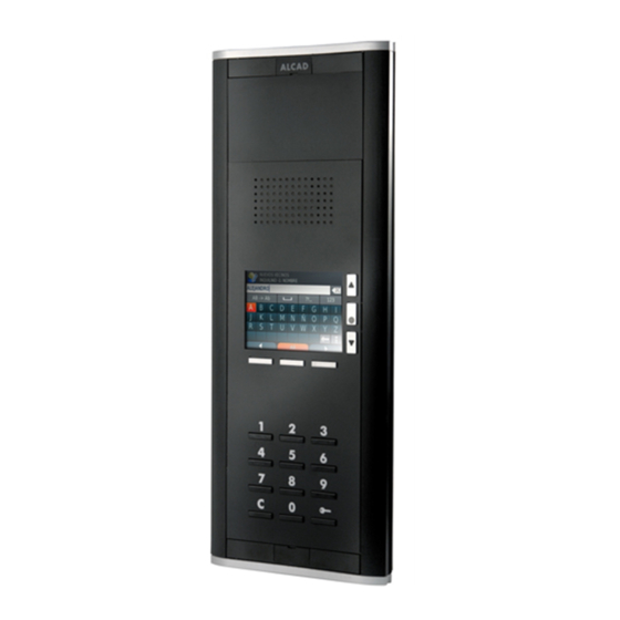
2 - W I R E D O O R E N T R Y S Y S T E M S iBLACK entrance panel with 2-wire audio unit, generic colour video iBLACK entrance panel with 2-wire audio unit, TFT screen, electronic unit, TFT screen, electronic directory and keypad directory and keypad Audio unit, 2-wire system (does not include speaker and microphone... -
Página 4: Operation
2 - W I R E D O O R E N T R Y S Y S T E M S OPERATION - MAKING A CALL TO A FLAT - To make a call to a dwelling, key in its code on the keypad of the entrance panel. The code which is entered is shown at the top of the entrance panel screen. - Página 5 2 - W I R E D O O R E N T R Y S Y S T E M S ACTIVATING THE ELECTRIC LOCK FROM THE ENTRANCE PANEL On the main screen, press the key marked . The message “Door opening” will appear on the screen. Next, enter one of the door-opening codes previously configured.
-
Página 6: Overview Of The Installation: Wiring
2 - W I R E D O O R E N T R Y S Y S T E M S OVERVIEW OF THE INSTALLATION: WIRING 2-WIRE DOOR ENTRY SYSTEM For distances, number of devices, or types of cable different from those shown in the tables, additional elements may be necessary (e.g. BUS voltage regenerators, signal amplifiers, etc.). - Página 7 2 - W I R E D O O R E N T R Y S Y S T E M S 2-WIRE VIDEODOOR ENTRY SYSTEM For distances, number of devices, or types of cable different from those shown in the tables, additional elements may be necessary (e.g. BUS voltage regenerators, signal amplifiers, etc.).
- Página 8 2 - W I R E D O O R E N T R Y S Y S T E M S 2-WIRE DOOR ENTRY SYSTEM WITH SPLITTER For distances, number of devices, or types of cable different from those shown in the tables, additional elements may be necessary (e.g. BUS voltage regenerators, signal amplifiers, etc.).
- Página 9 2 - W I R E D O O R E N T R Y S Y S T E M S 2-WIRE VIDEODOOR ENTRY SYSTEM WITH SPLITTER For distances, number of devices, or types of cable different from those shown in the tables, additional elements may be necessary (e.g. BUS voltage regenerators, signal amplifiers, etc.).
-
Página 10: Basic Installation
2 - W I R E D O O R E N T R Y S Y S T E M S BASIC INSTALLATION - SINGLE-WIRED DIAGRAM. 8 DWELLINGS B2 B1 DIV-054 cod.9730070 B1B2 B1B2 B1B2 B1B2 B1B2 B1B2 DIV-054 cod.9730070 B1B2 B1B2 B1B2 B1B2 B1B2 B1B2 Connection bracket depending on the type of monitor... - Página 11 2 - W I R E D O O R E N T R Y S Y S T E M S BASIC INSTALLATION - WIRED DIAGRAM DIV-054 cod.9730070 B2 B1 B1B2 B1B2 B1B2 B1B2 B1B2 B1B2 DIV-054 cod.9730070 B1B2 B1B2 B1B2 B1B2 B1B2 B1B2 GRF-302 cod.
-
Página 12: Basic Installation With Splitter. 2 Rises
2 - W I R E D O O R E N T R Y S Y S T E M S BASIC INSTALLATION WITH SPLITTER. 2 RISES SINGLE-WIRED DIAGRAM. 8 DWELLINGS B2 B1 B2 B1 DIV-054 DIV-054 cod.9730070 cod.9730070 B1B2 B1B2 B1B2 B1B2 B1B2 B1B2 B1B2 B1B2 B1B2 B1B2 B1B2 B1B2 DIV-154... - Página 13 2 - W I R E D O O R E N T R Y S Y S T E M S BASIC INSTALLATION WITH SPLITTER. 2 RISES WIRED DIAGRAM DIV-054 cod.9730070 DIV-054 B2 B1 cod.9730070 B2 B1 B1B2 B1B2 B1B2 B1B2 B1B2 B1B2 B1B2 B1B2 B1B2 B1B2 B1B2 B1B2 DIV-154 cod.
-
Página 14: Installation With 2 Points Of Entry
2 - W I R E D O O R E N T R Y S Y S T E M S INSTALLATION WITH 2 POINTS OF ENTRY SINGLE-WIRED DIAGRAM. 8 DWELLINGS B2 B1 DIV-054 cod.9730070 B1B2 B1B2 B1B2 B1B2 B1B2 B1B2 DIV-054 cod.9730070 B1B2 B1B2 B1B2 B1B2 B1B2 B1B2... - Página 15 2 - W I R E D O O R E N T R Y S Y S T E M S INSTALLATION WITH 2 POINTS OF ENTRY WIRED DIAGRAM. 8 DWELLINGS DIV-054 cod.9730070 B2 B1 B1B2 B1B2 B1B2 B1B2 B1B2 B1B2 DIV-054 cod.9730070 B1B2 B1B2 B1B2 B1B2 B1B2 B1B2...
-
Página 16: How To Connect The Audio Unit To The Keypad Panel
2 - W I R E D O O R E N T R Y S Y S T E M S HOW TO CONNECT THE AUDIO UNIT TO THE KEYPAD PANEL HOW TO CONNECT Entrance panel Audio unit KPD-521 cod. -
Página 17: Programming Instructions
2 - W I R E D O O R E N T R Y S Y S T E M S HOW TO CONNECT THE PANEL WITH DIRECTORY KPD-521 cod. 9650015 RVE-018 cod.9770054 – Ctrl2 Ctrl2 trl2 Permanent lighting Lighting of the panel with directory PROGRAMMING INSTRUCTIONS DESCRIPTION... - Página 18 2 - W I R E D O O R E N T R Y S Y S T E M S PROGRAMMING STEPS If the device that you wish to programme is a telephone, begin at step 3. If it is a monitor, begin at step 1. In the case of a monitor: Connect the monitor cable strip in the connections bracket In the case of a monitor: For greater ease, you can lean the monitor against the connections bracket.
- Página 19 2 - W I R E D O O R E N T R Y S Y S T E M S - PROGRAMMING STEPS - Steps 1 and 2 only when programming a monitor. For telephones, begin at step 3. Maximum time limit Bracket/telephone programmed Maximum time limit...
-
Página 20: Extending Installations
2 - W I R E D O O R E N T R Y S Y S T E M S EXTENDING INSTALLATIONS Electric lock - Connection - Activation - Standard electric lock Inverse electric lock Power supply for AC electric lock From the dwelling External pushbuttons Power supply... -
Página 21: Installing And Adjustment Instructions
2 - W I R E D O O R E N T R Y S Y S T E M S INSTALLING AND ADJUSTMENT INSTRUCTIONS - RECOMMENDATIONS - Before fixing the entrance panel to the pins of the flush-mounted box, put the audio unit in position and make the connections. It is much easier to make the connections in this way. - Página 22 2 - W I R E D O O R E N T R Y S Y S T E M S Configure the entrance panel. See "Entrance panel with keypad configuration instructions", page 23. Make the connections between the audio unit and the different elements of the panel (pushbuttons, speaker-microphone module, camera module, etc.).
-
Página 23: Entrance Panel With Keypad Configuration Instructions
2 - W I R E D O O R E N T R Y S Y S T E M S ENTRANCE PANEL WITH KEYPAD CONFIGURATION INSTRUCTIONS DESCRIPTION - The entrance panel with keyboard and electronic directory leaves the factory with the following characteristics: Ready to use: - In a standard installation (building with a single entrance or access point) - With pre-set operating characteristics (answering time, activation time of electric lock, etc.). - Página 24 2 - W I R E D O O R E N T R Y S Y S T E M S Modify factory defaults Installer menu Enter electronic directory STEPS FOR ACCESSING THE INSTALLER MENU With the main screen displayed on the screen, press the keys simultaneously.
- Página 25 2 - W I R E D O O R E N T R Y S Y S T E M S STEPS FOR ACCESSING THE INSTALLER MENU - Previous Main screen Select Next Maximum time limit MASTER code Error message Código incorrecto Incorrect code Code erroné...
- Página 26 2 - W I R E D O O R E N T R Y S Y S T E M S CONFIGURATION OF THE ENTRANCE PANEL TYPE OF INSTALLATION AND RANGE OF PROGRAMMING CODES OF TELEPHONES/ CONNECTION BRACKETS If you wish to assign a number between 1 and 9999 to the telephones/connection brackets, or if the panel is going to be working in an installation which is not standard, you will have to reconfigure the entrance panel before programming these devices.
- Página 27 2 - W I R E D O O R E N T R Y S Y S T E M S INSTALATION WITH SEVERAL POINTS OF ENTRY Note: Determine the main entrance panel; panel from which the monitors/telephones will be programmed. INSTALLATION PARAMETERS CONFIGURATION OF THE MAIN ENTRANCE PANEL (P) Description...
-
Página 28: Operating Parameters
2 - W I R E D O O R E N T R Y S Y S T E M S OPERATING PARAMETERS Description Default value Change the value in… Call settings Repetitions of the call tone Configuration Call settings Maximum conversation time (seconds) Answering time (seconds) Activation of electric lock... - Página 29 2 - W I R E D O O R E N T R Y S Y S T E M S VISITOR: SCREENS SCREEN FLOW Space for text Initial help screen "Initial message" screen Operating mode: Basic Operating mode: Normal Electronic directory "Search"...
- Página 30 2 - W I R E D O O R E N T R Y S Y S T E M S "INITIAL MESSAGE" SCREEN DESCRIPTION Possibility, with the system in stand-by mode, of displaying an informative text on the screen. This text will be shown on screen, alternating with the initial help screen.
-
Página 31: Main Screen
2 - W I R E D O O R E N T R Y S Y S T E M S MAIN SCREEN Basic operating mode Shows electronic directory (see on page 33) Normal operating mode Default value Shows help screen Shows the call options (see page 32) Normal operating mode Configuration options... - Página 32 2 - W I R E D O O R E N T R Y S Y S T E M S CALL OPTIONS SCREEN Default value Find last name Call by code Shows help screen Description Disable the option in… Search for resident Configuration System...
-
Página 33: Electronic Directory
2 - W I R E D O O R E N T R Y S Y S T E M S CHANGE THE MASTER CODE - Open the installer menu. See page 24. Select ' Configuration' Select 'System' Select 'MASTER code' Installer menu (page 24) "Configuration"... - Página 34 S Y S T E M S STEPS FOR GENERATING THE ELECTRONIC DIRECTORY Use the purpose-made ALCAD software to create the electronic directory on a PC. Transfer the modified file to the root folder of the USB memory stick. Plug the USB memory stick into the USB connector of the entrance panel. This connector is located in the rear part of the panel.
- Página 35 Remove the USB memory stick. Transfer the file to a PC and modify the information contained in the electronic directory using the purpose-made ALCAD software. Transfer the modified file to the USB memory stick and import it once again into the entrance panel. See page 34.
- Página 36 2 - W I R E D O O R E N T R Y S Y S T E M S STEPS FOR MODIFYING THE ELECTRONIC DIRECTORY ON A PC "Electronic directory" "USB" "Import/export" Installer menu (page 24) Page 34 "Export"...
-
Página 37: Administrator Menu
2 - W I R E D O O R E N T R Y S Y S T E M S ADMINISTRATOR MENU DESCRIPTION From the administrator menu, you can only access and modify the following information: name, surname and door-opening code of all residents. The entrance panel leaves the factory with a pre-set ADMINISTRATOR code (factory default ADMINISTRATOR code) which allows you to access this menu, provided that you have enabled this option from the installer menu. - Página 38 2 - W I R E D O O R E N T R Y S Y S T E M S STEPS FOR ACCESSING THE ADMINISTRATOR MENU With the main screen displayed on the screen, press the right and left lower keys simultaneously.
-
Página 39: Technical Characteristics
2 - W I R E D O O R E N T R Y S Y S T E M S TECHNICAL CHARACTERISTICS Note: Reference values are provided only to enable the checking of equipment and are reliable. Do not use the terminals of the equipment to feed additional devices without first consulting the manufacturer. -
Página 40: Power Supply
2 - W I R E D O O R E N T R Y S Y S T E M S - TFT CONTROLLER/KEYPAD KPD-521 Voltage POWER SUPPLY Current Operating temperature -... -
Página 41: Trouble Shooting
2 - W I R E D O O R E N T R Y S Y S T E M S TROUBLE SHOOTING To program the connection brackets/telephones, make sure that you check the connection of this panel with the other panels. If no fault is are doing so in the main entrance panel of the building (See "Entrance detected, the audio unit of this panel may be defective. - Página 42 2 - W I R E D O O R E N T R Y S Y S T E M S...
- Página 43 2 - W I R E D O O R E N T R Y S Y S T E M S...
- Página 44 2 - W I R E D O O R E N T R Y S Y S T E M S 21 Dec 2013...