Tabla de contenido
Publicidad
Enlaces rápidos
SERVICE MANUAL
System
DVD recorder section
Laser
Semiconductor laser
Audio recording format
Dolby Digital
Video recording format
MPEG Video
VCR section
Format
VHS NTSC standard
Video recording system
Ro
tary head helical scanning
FM system
Video heads
Double azimuth four heads
Video signal
NTSC color, EIA standards
Tape speed
3
SP: 33.35 mm/s (1
/
inches/s)
8
7
EP: 11.12 mm/s (
/
inches/s)
16
11
LP: 16.67 mm/s (
/
inches/s),
16
playback only
SPECIFICATIONS
Maximum recording/playback time
8 hrs. in EP mode (with T-160 tape)
Rewind time
Approx. 1 min (with T-120 tape)
Tuner section
Channel coverage
VHF 2 to 13
UHF 14 to 69
CATV A-8 to A-1, A to W, W+1 to
W+84
Antenna
75-ohm antenna terminal for VHF/UHF
Timer section
Clock
Quartz locked
Timer indication
12-hour cycle
Timer setting
12 programs in total (max.)
RDR-VX500
Mexican Model
Refer to the SERVICE MANUAL of VHS MECHANI-
CAL ADJUSTMENT MANUAL VII for MECHANICAL
ADJUSTMENTS. (9-921-790-11)
Inputs and outputs
LINE 1 IN and LINE 2 IN
VIDEO IN, phono jack (1 each)
Input signal: 1 Vp-p, 75 ohms,
unbalanced, sync negative
AUDIO IN, phono jacks (2 each)
Input level: 327 mVrms
Input impedance: more than 47 kilohms
LINE 2 IN
S VIDEO, 4-pin, mini-DIN jack
Y: 1.0 Vp-p, unbalanced, sync negative
C: 0.286 Vp-p, load impedance 75 ohms
DV IN, 4-pin jack, i.LINK S100
LINE OUT
VIDEO OUT, phono jack (1)
Output signal: 1 Vp-p, 75 ohms,
unbalanced, sync negative
AUDIO OUT, phono jacks (2)
Standard output: 327 mVrms
Load impedance: 47 kilohms
Output impedance: less than 10 kilohms
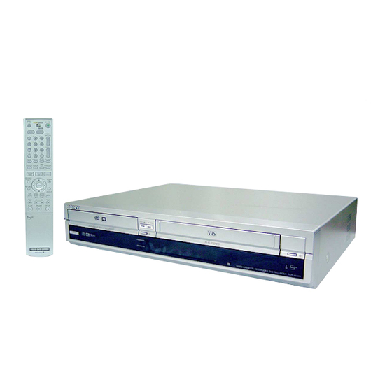
VIDEO CASSETTE RECORDER/
DVD RECORDER
RMT-V505
TS-10 MECHANISM
— Continued on next page —
Publicidad
Capítulos
Tabla de contenido

Resumen de contenidos para Sony RDR-VX500
- Página 1 RDR-VX500 RMT-V505 SERVICE MANUAL Mexican Model TS-10 MECHANISM Refer to the SERVICE MANUAL of VHS MECHANI- CAL ADJUSTMENT MANUAL VII for MECHANICAL ADJUSTMENTS. (9-921-790-11) SPECIFICATIONS Inputs and outputs Maximum recording/playback time System 8 hrs. in EP mode (with T-160 tape)
- Página 2 DIGITA L AUDIO OUT General Dimensions including projecting parts and controls (w/h/d) OPTICAL, Optical output jack Power requirements Approx. 430 × 85 × 334 mm −18 dBm (wave length: 660 nm) 120 V AC, 60 Hz (Approx. 17 × 3.4 × 13 inches) COAXIAL, phono jack Power consumption...
- Página 3 REPLACE THESE COMPONENTS WITH SONY PARTS It is best to use only unleaded solder but unleaded solder may WHOSE PART NUMBERS APPEAR AS SHOWN IN THIS also be added to ordinary solder. MANUAL OR IN SUPPLEMENTS PUBLISHED BY SONY. — 3 —...
-
Página 4: Tabla De Contenido
TABLE OF CONTENTS Precautions The Table of Cleaning, Lubrication and Replacement Time about Principal Parts ····················· 2-21 Safety Precautions ······························································ 5 Servicing Precautions ························································ 7 Block Diagram ............3-1 ESD Precautions ································································· 8 Handling the Optical Pick-up ············································· 9 PCB Diagrams General VCR Main PCB ·······························································... -
Página 5: Safety Precautions
PRECAUTIONS 1 SAFETY PRECAUTIONS 1) Before returning an instrument to the customer, always make a (4) Insulation Resistance Test Cold Check-(1) Unplug the power safety check of the entire instrument, including, but not limited supply cord and connect a jumper wire between the two prongs to, the following items: of the plug. - Página 6 6) Product Safety Notice-Some electrical and mechanical parts have special safety-related characteristics which are often not evident from visual inspection, nor can the protection they give necessarily be obtained by replacing them with components rated for higher voltage, wattage, etc. Parts that have special safety characteristics are identified by shading, an ( ) or a ( ) on...
-
Página 7: Servicing Precautions
2 SERVICING PRECAUTIONS CAUTION: Before servicing units covered by this service manual 2-2 Insulation Checking Procedure and its supplements, read and follow the Safety Precautions section of this manual. Disconnect the attachment plug from the AC outlet and turn the power ON. -
Página 8: Esd Precautions
3 ESD PRECAUTIONS Electrostatically Sensitive Devices (ESD) Some semiconductor (solid state) devices can be damaged easily by static electricity. Such components commonly are called Electrostatically Sensitive Devices (ESD). Examples of typical ESD devices are integrated circuits and some field-effect transistors and semiconductor chip components. -
Página 9: Handling The Optical Pick-Up
4 HANDLING THE OPTICAL PICK-UP The laser diode in the optical pick up may suffer electrostatic breakdown because of potential static electricity from clothing and your body. The following method is recommended. (1) Place a conductive sheet on the work bench (The black sheet used for wrapping repair parts.) (2) Place the set on the conductive sheet so that the chassis is grounded to the sheet. - Página 10 MEMO — 10 —...
-
Página 11: General
RDR-VX500 1. GENERAL This section is extracted from instruction manual. (2-586-732-11) Acerca de este manual Icono Significado Modos de utilización de la videograbadora/grabadora de • Las instrucciones de este manual describen los controles del mando Funciones disponibles para los DVD+RW DVD (videodisco digital) a distancia. - Página 12 NTSC (comité nacional de sistema de Tipo utilizado en Características del disco este manual televisión), tal como PAL (línea de fase RDR-VX500 MX alternativa) o SECAM (memoria y color secuenciales) DVD VIDEO Discos tales como los de películas que pueden (videodisco adquirirse o alquilarse z Observación...
-
Página 13: Conexiones Y Ajustes
Notas Reproducción Cintas VHS (sistema • Algunos DVD+RW/DVD+R (videodisco digital más La VCR (videograbadora) identifica doméstico de video) que regrabable/videodisco digital más grabable), DVD- automáticamente el sistema de grabación y el RW/DVD-R (videodisco digital menos regrabable/ pueden grabarse y modo de grabación (SP (reproducción estándar) o videodisco digital menos grabable) o CD-RW/CD-R (disco compacto regrabable/disco compacto grabable) EP (reproducción extendida) (3×)) de las cintas... -
Página 14: Paso 3: Conexión Al Televisor
B: Decodificador de cable con salida de antena solamente C: Cable sin decodificador de cable o antena solamente (sin televisión por cable) Con esta conexión, puede grabar cualquier canal del receptor satelital o decodificador de cable. Asegúrese de que el receptor satelital o decodificador de cable está encendido. Utilice esta conexión si ve canales de cable sin decodificador de cable. -
Página 15: Paso 4: Conexión Al Amplificador (Receptor) De Av (Audiovisual)
Si el televisor tiene toma de entrada de S video Si el televisor tiene tomas de entrada de video componente Conecte un cable de S video (no suministrado). Disfrutará de imágenes de alta calidad. Conecte las tomas COMPONENT VIDEO OUT (salida de video componente) utilizando un cable de Cuando conecte la grabadora utilizando esta conexión, realice las conexiones de audio empleando las video componente (no suministrado) o tres cables de video (no suministrados) del mismo tipo y longitud. -
Página 16: A Conexión A Las Tomas De Entrada De Audio L/R (Izquierda/Derecha)
• Si el mando a distancia suministrado interfiere con otro reproductor de DVD (videodisco digital)/ Sony 01 (predeterminado) videograbadora o videograbadora/grabadora de DVD CH (canal) +/– (videodisco digital) Sony, cambie el número del modo Botones Akai VOL (volumen) numéricos, de comando de esta grabadora (página 33). -
Página 17: Paso 7: Instalación Fácil
DVD (videodisco digital)/ Ajuste del reloj Temporizador numéricos. videograbadora o videograbadora/grabadora de Vídeo Proscan DVD (videodisco digital) Sony, ajuste el número Editar Audio Suelte "/1. Quasar 06, 18 del modo de comando de esta grabadora y del Características... -
Página 18: Configuración Del Sistema
Pulse ENTER (introducir). Seleccione “Instalación”, y pulse ENTER Introduzca el número de canal de Configuración del sistema (introducir). televisión utilizando M/m. Aparece la pantalla de configuración para seleccionar el tipo de señal DTS (sistema ® VCR Plus+ (grabación de Instalación 10:10 AM Preajuste de sintonizador 10:10 AM... -
Página 19: (Sistema Doméstico De Video)
Encienda el televisor. Notas Pulse "/1. • No conecte la toma LINE IN (VIDEO) (entrada de línea de video) amarilla cuando utilice un cable de S video. Operaciones básicas Se enciende la grabadora. • No conecte la toma de salida de esta grabadora a la toma de entrada de otro equipo con la toma de salida del otro equipo conectada a la toma de entrada de esta grabadora. -
Página 20: Utilización De Los Menús De Pantalla
Pulse REC MODE (modo de grabación) Inserte una cinta provista de lengüeta de Grabación de un programa Utilización de los menús de varias veces para seleccionar el modo de seguridad. grabación. a una cinta VHS (sistema pantalla Cada vez que pulse el botón, la indicación en doméstico de video) la pantalla del televisor cambiará... -
Página 21: Utilización De La Lista De Títulos
Pulse Z OPEN/CLOSE (apertura/cierre) Para quitar la Lista de títulos Utilización de la lista de Utilización de las pantallas para cerrar la bandeja de discos. Pulse TITLE LIST (lista de títulos). Espere hasta que “LOAD” (carga) títulos de ajuste de DVD desaparezca de la pantalla del panel frontal. -
Página 22: Comprobación De La Información Y El Tiempo De Reproducción
Para anular la finalización de un DVD-RW Pulse DISPLAY (pantalla). Comprobación del tiempo de Comprobación de la (modo VR) (videodisco digital menos Aparece la pantalla de información. reproducción/tiempo restante regrabable (modo de grabación de video)) Para apagar la pantalla de información, pulse información y el tiempo de DISPLAY (pantalla) varias veces. -
Página 23: Grabación De Dvd
Pulse DVD (videodisco digital) para Imágenes que no pueden grabarse Nota Grabación de DVD controlar la grabadora de DVD (videodisco Los siguientes casos pueden producir ligeras digital). En esta grabadora no pueden grabarse imágenes (videodisco digital) sin el inexactitudes en el tiempo de grabación. con protección contra copias. -
Página 24: Grabación De Dvd (Videodisco Digital) Con El Tempolizador
Pulse (temporizador). Pulse ENTER (introducir). Ajuste manual del temporizador Grabación de DVD Aparece el menú de la Lista de temporizador (estándar) Temporizador – Estandar 10:10 AM (página 66). Se ilumina el indicador c en la (videodisco digital) con el pantalla del panel frontal, y la grabadora está No Rec To Date Start... -
Página 25: Grabación Desde Un Equipo Conectado Que Tiene Temporizador (Grabación Sincronizada)
Pulse DVD (videodisco digital) para Ajuste el temporizador del equipo Notas Grabación desde un equipo controlar la grabadora de DVD (videodisco conectado a la hora del programa que • La grabadora comienza a grabar solamente después de digital). quiera grabar, y apáguelo. conectado que tiene detectar la señal de video procedente del equipo conectado. -
Página 26: Reproducción
Al mismo tiempo, pulse z REC Pulse INPUT SELECT (selección de Pulse DVD (videodisco digital) para entrada) para seleccionar una fuente de (grabación) en esta grabadora y el botón controlar la grabadora de DVD (videodisco Reproducción de discos entrada en función de la conexión que de pausa o reproducción en el equipo digital). - Página 27 Opciones de reproducción Botones Operaciones Discos SURROUND Selecciona uno de los efectos cuando se pulsa varias veces. - RW (sonido “No”: Sin efecto de sonido envolvente - RW Z OPEN/CLOSE Video envolvente) “Surround1”: Crea un conjunto de altavoces envolventes (apertura/cierre) virtuales.
- Página 28 Seleccione un método de búsqueda. Búsqueda de títulos/ Reproducción de pistas de “Título” (para DVD (videodisco digital)) “Capítulo” (para DVD (videodisco digital)) capítulos/pistas, etc. audio MP3 (capa de audio 3 “Pista” (para VIDEO CD (videodisco compacto) con función PBC (control de del grupo de expertos en reproducción) desactivada) - RW...
-
Página 29: Grabación De Videocasetes Sin El Temporizador
Pulse DVD (videodisco digital) para Para reproducir la secuencia de imágenes Pulse </, para seleccionar la velocidad de Para reproducir un CD multisesión (disco controlar la grabadora de DVD (videodisco reproducción deseada, después pulse ENTER compacto multisesión) Pulse H PLAY (reproducción). (introducir). - Página 30 Pulse VIDEO (video) para controlar la Grabación utilizando la función Comprobación del tiempo restante Grabación de videocasetes videograbadora. Quick Timer (temporizador rápido) Pulse DISPLAY (pantalla). con temporizador (Estándar/ Inserte una cinta provista de lengüeta de (Grabación con temporizador seguridad. VCR Plus+ (grabación de pulsando un solo botón) Parar videocasetes Plus))
- Página 31 z Observación Pulse REC MODE (modo de grabación) Si aparece el menú de programación del El menú de programación del temporizador también Grabación desde un equipo temporizador (Estandar), presione < para varias veces para seleccionar la velocidad puede mostrarse de la siguiente manera: cambiar la indicación en pantalla a “VCR de cinta, “SP”...
-
Página 32: Grabación Desde Un Equipo Conectado Que No Tiene Temporizador
Pulse INPUT SELECT (selección de Para expulsar la cinta Grabación desde un equipo Pulse Z OPEN/CLOSE (apertura/cierre). entrada) para seleccionar una fuente de Reproducción de cintas VHS (sistema entrada en función de la conexión que doméstico de video) conectado que no tiene Para desconectar la alimentación durante el haya hecho. -
Página 33: Búsqueda Utilizando Varias Funciones
Notas Búsqueda del punto 0:00:00 del Búsqueda utilizando varias • El sonido estará enmudecido durante la reproducción a varias velocidades. contador funciones • La imagen puede aparecer con ruido al reproducirse a alta velocidad en sentido inverso. Para marcar un punto de la cinta que desee localizar posteriormente, reajuste el contador de La videograbadora marca la cinta cinta a “0:00:00”. -
Página 34: Edición De Dvd (Videodisco Digital)
Ejemplo: Grabó los últimos partidos de un Opciones de edición para DVD-RW Edición de un título campeonato de fútbol en un DVD-RW (videodisco Edición de DVD (videodisco digital) (modo VR) (videodisco digital menos digital menos regrabable) (modo VR) (videodisco digital menos regrabable (modo de video)). Desea regrabable (modo de grabación de Antes de editar - RW... -
Página 35: Creación De Una Playlist (Lista De Reproducción)
Pulse SYSTEM MENU (menú del sistema) Pulse ENTER (introducir) en el punto de Creación de una Playlist Edición de una Playlist mientras la grabadora está parada. finalización. Se selecciona “Hacer”. (lista de reproducción) (lista de reproducción) Lista de títulos (Original) 10:10 AM Para reponer el punto de inicio o finalización, Lista... -
Página 36: Duplicación De Un Dvd (Videodisco Digital) A Un Video
Pulse ENTER (introducir). Agregación de una escena (Añadir) Utilizando el botón T VIDEO (video) Duplicación (TAPE (cinta) La pantalla vuelve a la pantalla de “Edit. esc.”. de la grabadora La sección seleccionada se captura como una (videodisco digital)) - RW escena y se agrega antes de la escena Inserte un disco grabable. -
Página 37: Duplicación De Dv (Video Digital) (Dv (Video Digital) T Dvd (Videodisco Digital))
Seleccione “Editar”, y pulse ENTER Para seleccionar el sonido o idioma Conexión de una (introducir). Duplicación de DV (video digital) (DV Después del paso 5 anterior, pulse AUDIO (audio) varias veces para seleccionar el sonido que desee, (video digital) t DVD (videodisco digital)) videocámara digital a la Editar 10:10 AM... -
Página 38: Ajustes Y Regtajes
Seleccione “Audio”, y pulse ENTER Seleccione “Edición DV”, y pulse ENTER Notas (introducir). (introducir). • Si quiere reproducir el disco en otro equipo de DVD Aparecen la pantalla para grabar y “Modo (videodisco digital), finalice el disco (página 51). Audio 10:10 AM cinta DV”. -
Página 39: Ajuste Del Reloj
Preajuste automático Ajuste manual 3, 4 canales OUT (salida) Ajuste del reloj Programa automáticamente los canales que Programa o desactiva canales manualmente. Programe el canal de salida de RF pueden recibirse. Si algún canal no puede programarse utilizando la (radiofrecuencia) para que el televisor pueda La grabadora puede recibir los canales 2 a 13 en función de Preajuste automático o Instalación recibir la señal correcta procedente de la... -
Página 40: Ajustes De Audio (Audio)
Salida digital Audio DRC (control de gama dinámica) (DVD • DTS (sistema digital de sala de cine) (DVD Ajustes de audio (Audio) VIDEO (videodisco digital, video) solamente) (videodisco digital) solamente) Los siguientes elementos de configuración Selecciona sacar o no sacar señales DTS. cambian el método de salida de las señales de Hace que el sonido suene claro cuando se baja el audio cuando se conecta un componente, tal como... -
Página 41: Instalación Fácil (Restauración De La Grabadora)
Paterno 10:10 AM Aparece la configuración de “Opciones” con Crear contraseña 10:10 AM Lista DVD (videodisco digital) Sony” en la página 33. las opciones siguientes. Los ajustes Contraseña : On: Level 8 (Adults) Nivel 8 (Adultos) Lista de títulos de títulos... -
Página 42: Reproducción De Dvd (Videodisco Digital)
Seleccione un número de canal cuando Los indicadores parpadean después de vídeo Sony. Si en su área no hay disponible un grabe programas de TV; elija “LINE1” (línea 1) o No se ha grabado nada aunque ha configurado programar la grabación con temporizador. -
Página 43: Link Velocidad En Baudios
IEEE 1394 es una norma internacional normalizada por el Instituto de ingenieros Cable requerido i.LINK eléctricos y electrónicos. Utilice el cable Sony i.LINK 4 pines a 4 pines suciedad final (durante la duplicación DV (video digital)). inicial i.LINK y son marcas registradas. -
Página 44: Guía De Componentes Y Controles
Mando a distancia para DVD (videodisco digital) Guía de componentes y controles A TV/DVD·VIDEO (televisión/videodisco Los botones del mando a distancia tienen la misma función que los botones de la grabadora si tienen digital·video) interruptor (31) Para más información, consulte las páginas entre paréntesis. nombres iguales o similares. - Página 45 N Botón ?/1 (encendido/en espera) (34) Pantalla del panel frontal O Botón VIDEO (video) (41) P Botones CH (canal)*/TRACKING (seguimiento) +/– (44, 82, 94) Q Botones VOL (volumen) +/– (31) R Botón TV/VIDEO (televisión/video) (31) RW VR VCD STEREO VIDEO S Botón INPUT SELECT (selección de entrada) (44, 82) T Botón TOOLS (herramientas) (47)
-
Página 46: Idioma De Audio/Subtítulos
Idioma de audio/subtítulos de DVD (videodisco digital) Abreviatura Idioma Árabe Búlgaro Chino Croata Checo Danés Alemán Inglés Español Finlandés Francés Griego Húngaro Indonesio Hindi Islandés Italiano Hebreo Japonés Coreano Malayo Holandés Noruego Polaco Portugués Ruso Sueco Tailandés Turco Vietnamita Africano 1-36E... -
Página 47: Disassembly And Reassembly
RDR-VX500 2. DISASSEMBLY AND REASSEMBLY 2-1 CABINET AND PCB 2-1-1 Cabinet Top Removal 2-1-3 Ass’y Front Panel Removal Lift up the Cabinet Top in the direction of arrow. 1 REMOVE 1 RELEASE 3 HOOKS 3 SCREWS Fig. 2-3 Ass’y Front Panel Removal (Top View) Fig. -
Página 48: Chassis Removal
2-1-4 Chassis Removal 2 REMOVE 4 SCREWS 3 REMOVE 4 SCREWS 1 REMOVE 2 SCREWS VCR DECK DVD DECK 4 REMOVE 7 SCREWS VCR MAIN PCB SHIELD CASE-GROUND PCB JACK PCB DVD MAIN PCB DV INPUT PCB FUNCTION TIMER PCB Fig. -
Página 49: Circuit Board Locations
2-2 CIRCUIT BOARD LOCATIONS Fig. 2-7 Circuit Board Locations... -
Página 50: Vcr Deck Parts Locations
2-3 VCR DECK PARTS LOCATIONS 2-3-1 Top View Fig. 2-8 Top parts Location-1 1 GEAR FL CAM 2 MOTOR LOADING ASS’Y 3 LEVER FL ARM ASS’Y 4 HOLDER FL CASSETTE ASS’Y 5 LEVER FL DOOR 6 SLIDER FL DRIVE... - Página 51 9 q; qa q; qs Fig. 2-9 Top Parts Location-2 1 FE HEAD 8 DISK S REEL 2 CYLINDER ASS’Y 9 LEVER S BRAKE ASS’Y 3 ACE HEAD ASS’Y 0 GEAR IDLE 4 LEVER UNIT PINCH ASS’Y qa LEVER IDLE 5 LEVER #9 GUIDE ASS’Y qs LEVER T BRAKE ASS’Y 6 LEVER TENSION ASS’Y...
-
Página 52: Bottom View
2-3-2 Bottom View Fig. 2-10 Bottom Parts Location 1 GEAR JOINT 1 2 GEAR JOINT 2 3 BRAKET GEAR 4 MOTOR CAPSTAN ASS’Y 5 LEVER T LOAD ASS’Y 6 GEAR LOADING DRIVE 7 LEVER S LOAD ASS’Y 8 HOLDER CLUTCH ASS’Y 9 BELT PULLEY 0 SLIDER CAM... -
Página 53: Vcr Deck
2-4 VCR DECK 2-4-1 Holder FL Cassette Ass’y Removal 2-4-2 Lever FL Arm Ass’y Removal 1) Pull the Holder FL Cassette Ass’y 1 to the eject position. 1) Push the hole “A” in the direction of arrow “B” use the pin.(about 2) Pull the Holder FL Cassette Ass’y 1 as grasping the Holder FL Dia. -
Página 54: Lever Fl Door Removal
2-4-3 Lever FL Door Removal 2-4-4 Slider FL Drive, Gear FL Cam Removal 1) Release the Hook 2 and Remove the Lever FL Door 1 in the 1) Pull the Slider FL Drive 1 to the front direction. direction of arrow “A”. 2) Remove the Slider FL Drive 1 in the direction of arrow. -
Página 55: Gear Worm Wheel Removal
2-4-5 Gear Worm Wheel Removal 2-4-6 Cable Flat Removal 1) Remove the Gear Worm wheel 1. 1) Remove the Drum connecting part of Cable Flat 1 from Connector Wafer 2. 2) Remove the Loading Motor connecting part of Cable Flat 1 from Connector Wafer 3. -
Página 56: Motor Loading Ass'y Removal
2-4-7 Motor Loading Ass’y Removal 2-4-8 Bracket Gear, Gear Joint 2, 1 Removal 1) Remove the Screw 1. 1) Remove the Screw 1. 2) Remove the Motor Loading Ass’y 2. 2) Remove the Bracket Gear 2. 3) Remove the Gear Joint 2 3. 4) Remove the Gear Joint 1 4. -
Página 57: Gear Loading Drive, Slider Cam
2-4-9 Gear Loading Drive, Slider Cam, 2-4-10 Gear Loading Drive, Slider Cam, Lever Load S, T Ass’y Removal Lever Load S, T Ass’y Assembly 1) Remove the Belt Pulley. (Refer to Fig. 2-38) 1) When reinstalling, be sure to align dot of Lever Load T Ass’y 2) Remove the Gear Loading Drive 1 after releasing Hook [A] in 1 with dot of Lever Load S Ass’y 2 as shown in drawing, the direction arrow as shown in detail drawing. -
Página 58: Lever Pinch Drive, Lever Tension Drive Removal
2-4-11 Lever Pinch Drive, 2-4-12 Lever Tension Ass’y, Lever Tension Drive Removal Band Brake Ass’y Removal 1) Remove the Lever Pinch Drive 1, Lever Tension Drive 2. 1) Remove the Lever Brake S Ass’y (Refer to Fig 2-25). 2) Remove the Spring Tension Lever 1. 1 LEVER PINCH DRIVE 3) Rotate stopper of Main Base in the direction of arrow “A”. -
Página 59: Lever Brake S, T Ass'y Removal
2-4-13 Lever Brake S, T Ass’y Removal 2-4-14 Gear Idle Ass’y Removal 1) Push the Lever Idle 1 in the direction of arrow “A”, “B”. 1) Release the Hook [A] and the Hook [B], [C] in the direction of arrow as shown in Fig 2-25. 2) Lift the Lever Idle 1. -
Página 60: Disk S, T Reel Removal
2-4-15 Disk S, T Reel Removal 2-4-16 Holder Clutch Ass’y Removal 1) Lift the Disk S, T Reel 1, 2. 1) Remove the Washer Slit 1. 2) Lift the Holder Clutch Ass’y 2. Note: When you reinstall Holder Clutch Ass’y 1) Check the condition of spring as shown in detail A. -
Página 61: Lever Up Down Ass'y, Gear Center Ass'y Removal
2-4-17 Lever Up Down Ass’y, Gear Center 2-4-18 Guide Cassette Door Removal Ass’y Removal 1) Lift the Hook [A]. 2) Rotate the Guide Cassette Door 1 in the direction of arrow. 1) Remove the 2 hooks in the direction of arrow as shown Fig. 2- 29 and lift the Lever Up Down Ass’y 1. -
Página 62: Lever Unit Pinch Ass'y, Plate Joint
2-4-19 Lever Unit Pinch Ass’y, Plate Joint, 2-4-20 Lever #9 Guide Ass’y Removal Spring Pinch Drive Removal 1) Remove the Spring #9 Guide 1. 2) Lift the Lever #9 Guide Ass’y 2 in the direction of arrow “A”. 1) Lift the Lever Unit Pinch Ass’y 1. 2) Remove the Plate Joint 2 from Lever Pinch Drive. -
Página 63: Fe Head Removal
2-4-21 FE Head Removal 2-4-22 ACE Head Removal 1) Lift the FE Head 1. 1) Pull out the FPC from connector of ACE Head Ass’y 2. 2) Remove the Screw 1. 3) Lift the ACE Head Ass’y 2. 1 FE HEAD 1 SCREW HEAD ACE ASS`Y Fig. -
Página 64: Slider S, T Ass'y Removal
2-4-23 Slider S, T Ass’y Removal 2-4-24 Plate Ground Deck, Cylinder Ass’y Re- moval 1) Move the Slider S, T Ass’y 1, 2 to slot, and then lift it to remove. (Refer to arrow) 1) Remove the 3 Screws 1. 2) Lift the Plate Ground Deck 2. -
Página 65: Hook Capstan, Belt Pulley Removal
2-4-25 Hook Capstan, Belt Pulley Removal 2-4-26 Motor Capstan Ass’y Removal 1) Remove the Hook Capstan 1 after realeasing Hook in the 1) Remove the 3 Screws 1. direction arrow as shown in detail drawing. 2) Remove the Motor Capstan Ass’y 2. 2) Remove the Belt Pulley 2. -
Página 66: Post #8 Guide Ass'y Removal
2-4-27 Post #8 Guide Ass’y Removal 2-4-29 How to Eject the Cassette Tape (If the unit does not operate on condition 1) Rotate the Post #8 Guide Ass’y 1 in the direction of arrow to that is inserted into housing ass’y) lift up. -
Página 67: The Table Of Cleaning, Lubrication And Replacement Time About Principal Parts
2-5 THE TABLE OF CLEANING, LUBRICATION AND REPLACEMENT TIME ABOUT PRIN- CIPAL PARTS 1) The replacement time of parts is not life of parts. 2) The table 2-1 is that the VCR Set is in normal condition (normal temperature, normal humidity). The checking period may be changed owing to the condition of use, runtime and environmental conditions. - Página 68 MEMO 2-22E...
-
Página 69: Block Diagram
RDR-VX500 3. Block Diagram 4MB FLASH EEPROM 8MB(x2) SDRAM K8D3216UBM 24LC32 DVD-Rewritable Drive (32bit) (8bit) (I2C) ND-2500A/REC RF Out VHF/UHF TM BLOCK CVBS MTS IC 2MB(x4) SDRAM DVD V IN ENCODER 6CH AMP DECODER LA72670 (64bit) LA73054 CS92686 CS98202 L/R from Tuner... - Página 70 MEMO 3-4E...
-
Página 71: Pcb Diagrams
RDR-VX500 4. PCB Diagrams 4-1 VCR Main PCB - - - - - - - - - - - - - - - - - - - - - - - - - - - - - - - - - - - - - - - - 4-3... -
Página 72: Vcr Main Pcb
4-1 VCR Main PCB COMPONENT SIDE... - Página 73 CONDUCTOR SIDE...
-
Página 74: Dvd Main Pcb
4-2 DVD Main PCB COMPONENT SIDE... - Página 75 CONDUCTOR SIDE 4-10...
-
Página 76: Jack Pcb
4-3 Jack PCB COMPONENT SIDE 4-11 4-12... - Página 77 CONDUCTOR SIDE 4-13 4-14...
-
Página 78: Dv Input Pcb
4-4 DV Input PCB COMPONENT SIDE CONDUCTOR SIDE 4-5 Function Timer PCB COMPONENT SIDE CONDUCTOR SIDE 4-15 4-16E... -
Página 79: Schematic Diagrams
RDR-VX500 5. Schematic Diagrams Block Identification of Main PCB - - - - - - - - - - - - - - - - - - - - - - - - - - - - - - 5-3 Note 5-1 S.M.P.S (VCR Main PCB) - - - - - - - - - - - - - - - - - - - - - - - - - - - - - - - - - 5-5... -
Página 80: Block Identification Of Main Pcb
Block Identification of Main PCB VCR MAIN PCB <Component Side> <Conductor Side>... -
Página 81: Vcr Main Pcb)
5-1 S.M.P.S. (VCR Main PCB) MBRF10A0 MBRF10A0... -
Página 82: Power (Vcr Main Pcb)
5-2 Power (VCR Main PCB) (MX : IN5819) (MX : IN5819) -
Página 83: Logic (Vcr Main Pcb)
5-3 Logic (VCR Main PCB) MX : OPTION MX : OPTION 5-10... -
Página 84: A/V (Vcr Main Pcb)
5-4 A/V (VCR Main PCB) 5-11 5-12... -
Página 85: Hi-Fi (Vcr Main Pcb)
5-5 Hi-Fi (VCR Main PCB) 5-13 5-14... -
Página 86: Function Timer (Function Timer Pcb)
5-6 Function Timer (Function Timer PCB) 5-15 5-16... -
Página 87: Encoder (Dvd Main Pcb)
5-7 Encoder (DVD Main PCB) M D [31:0] C H ANG E Par t T ype( FB23, FB24, FB25, FB26) 3225 to 2012 C9 8 ADD R132, R133, C40 0,C 401( 041204) P3V3 P3V3 OPEN C400 0.01NF C401 0.01NF SM1V8 P3V3 FB2 3 FB2 4 ADD C98, R29 f or EM I modif y... -
Página 88: Decoder (Dvd Main Pcb)
5-8 Decoder (DVD Main PCB) V_ R _O U T V_R _O U T AD C _B C K [ 2,6] Y _G_ OUT Y_ G _O U T P C MI_L RCK [ 2 ,4 ] U_ B _O U T U_ B _O U T P C MI_D A T A [2,4]... -
Página 89: Video Decoder And Connector (Dvd Main Pcb)
5-9 Video Decoder and Connector (DVD Main PCB) Change Value 22pF to 33pF (C12,C13) 33pF Change Value 1M to 100K 14.318MHz (R54) Change Part Type(FB2,FB3,FB4,FB5) P3V3 VDEC_3V3D 33pF 100K 3225 to 2012 0(2012) 100uF/16V P1V8 VDEC_1V8D 0(2012) 100uF/16V VDEC_1V8A VDEC_3V3A IC301 0(2012) 0(2012) -
Página 90: Dv Interface And 1394 Connector (Dvd Main Pcb)
5-10 DV Interface and 1394 Connector (DVD Main PCB) Chang e V alue 27pF t o 20pF (C 1,C 2) P3V3 2 4 .576M H Z Add C228 f or ESD M odify C L = 20p F C2 2 8 2 0pF 2 0pF OPEN... -
Página 91: Audio Dac And Adc (Dvd Main Pcb)
5-11 Audio DAC and ADC (DVD Main PCB) Chang e Par t T ype( F B 16,F 17) 3225 t o 2012 P12V0 P3V3 P3V3_ D IG P5V0_ D IG FB1 6 FB1 7 0(2012) 0(2012) C1 8 5 C 1 8 3 0 .1 u F/25V/Y 5V C 1 8 4 0 .1 u F/25V/Y 5V R 1 48... -
Página 92: Connectors And Power (Dvd Main Pcb)
5-12 Connectors and Power (DVD Main PCB) CN 3 5V to 3 .3V reg ulator fo r T I T V P 5146 ( 278R33 Fairchild) CN 1 G N D P3V3 G N D V 3 .3 LINE2 V IN OR (3216) V 3 .3 AVI N(F R I) -
Página 93: Mts/Tuner (Jack Pcb)
5-13 Mts/Tuner (JACK PCB) 5-29 5-30... -
Página 94: Av In/Out (Jack Pcb)
5-14 AV IN/OUT (JACK PCB) 5-31 5-32... -
Página 95: Component/Super Out (Jack Pcb)
5-15 Component/Super Out (JACK PCB) 5-33 5-34... - Página 96 MEMO 5-36E...
-
Página 97: Alignment And Adjustments
RDR-VX500 6. ALIGNMENT AND ADJUSTMENTS 6-1 VCR ADJUSTMENT 6-1-1 Reference 1) X-Point (Tracking center) adjustment, “Head switching adjustment” can be adjusted with remote control. 2) When replacing the Main PCB Micom (IC601) and NVRAM (IC603: EEPROM) be sure to adjust the “Head switching adjustment”. - Página 98 6-1-1(b) TEST location for adjustment mode setting Short-Circuit for few seconds and release. (Just one time) Fig. 6-2 Function Timer PCB (Top View)
-
Página 99: Head Switching Point Adjustment
6-1-2 Head Switching Point Adjustment 1) Playback the alignment tape. 2) Intermittently short-circuit the two Test Points on Function Timer PCB while setting the adjustment mode. (See Fig. 6-2) 3) Press the “1, 0” buttons ; remote control adjustment operates automatically. (See Fig. 6-1) -
Página 100: Vcr Mechanical Adjustment
6-2 VCR MECHANICAL ADJUSTMENT 6-2-1 Tape Transport System and Adjustment Locations The tape transport system has been adjusted precisely in the factory. Alignment is not necessary except for the following : 1) Noise observed on the screen. 2) Tape damage. 3) Parts replacement in the tape transport system. -
Página 101: Tape Transport System Adjustment
6-2-2 Tape Transport System Adjustment When parts are replaced, perform the required adjustments by referring to procedures for the tape transport system. If there are any changes to the tape path, first run a T-120 tape and make sure excessive tape wrinkle does not occur at the tape guides. If tape wrinkle is observed at the guide roller S, T, turn the guide roller S, T until wrinkle disappears. - Página 102 b. ACE HEAD TILT ADJUSTMENT 1) Playback a blank tape and observe the position of the tape at the lower flange of tape guide. 2) Confirm that there is no curl or wrinkle at the lower flange of tape guide as shown in Fig. 6-7 (B). 3) If a curl or wrinkle of the tape occurs, slightly turn the screw (A) tilt adjust on the ACE head ass’y.
- Página 103 d. ACE HEAD POSITION (X-POINT) ADJUSTMENT 1) Playback the alignment tape (Color bar) 2) Intermittently short-circuit the two Test Points on Function Timer PCB. (See Fig. 6-2) 3) Press the “0, 5” remote control buttons, then adjustment is operates automatically. (See Fig. 6-1) 4) Connect the CH-1 probe to “Envelope”...
-
Página 104: Note
(2) Linearity adjustment (Guide roller S, T adjustment) 1) Playback the Mono Scope alignment tape (SP mode). 2) Observe the video envelope signal on an oscilloscope (triggered by the video switching pulse). 3) Make sure the video envelope waveform (at its minimum) meets the specification shown in Fig. 6-9. If it does not, adjust as follows : Note: a=Maximum output of the video RF envelope. - Página 105 6) Play back the Mono Scope alignment tape (SP mode). 7) Connect an oscilloscope CH-1 to the “Envelope” and CH-2 to the “H’D SW Pulse” for triggering. 8) Turn the guide roller heads with a flat head ( ) driver to obtain a flat video RF envelope as shown in Fig. 6-11. IDEAL ENVELOPE S HEIGHT TOO HIGH T HEIGHT TOO HIGH...
-
Página 106: Reel Torque
(4) Envelope Check 1) Make recordings on T-120 (E-120) and T-160 (E-180) tape. Make sure the playback output envelope meets the specification as shown in Fig. 6-13. 2) Play back a self recorded tape (recording made on the unit using with T-120 (E-120). The video envelope should meet the specification as shown in Fig. - Página 107 No Power Detected Key Operation or (stand by LED OFF) Remote Control Error Is the measurement of F1S01 is normal? Change fuse Check power and front connector power with in normal value? Change short circuited or BD01~04, ZD1S01~2 XT601 14.318MHz Check the circuity around the clock opened parts SHORT and OPEN...
- Página 108 PLAY MODE MECHANISM DOESN'T (VCR Section) (VCR Section) INOPERATIVE OPERATE IN PLAY MODE TURN VCR POWER ON EE-VIDEO (VIDEO MISSING IN EE MODE) LOAD A TAPE AND PRESS PLAY BUTTON INSERT THE CASETTE TAPE RECORDED BY ANOTHER VCR AND PRESS PLAY BUTTON (LOAD) CHECK IC601-59:HIGH...
- Página 109 RECORD MODE (VCR Section) DOESN'T OPERATE CAPSTAN (CAPSTAN DOES NOT ROTATION ROTATE) PLAY (PLAY MODE OPERATION DOESN'T OPERATE) LOAD VCR WITH A TAKE UP REEL SENSOR (S.T REEL) BLANK TAPE AND SUPPLY REEL SENSOR PRESS RECORD BUTTON IC601-1.2 (PT601.PT602) PULSE EJECT CHANGE TAPE REC MODE...
- Página 110 FAST FORWARD FWD SEARCH DOESN'T (VCR Section) (VCR Section) DOESN'T OPERATE OPERATE LOAD TAPE AND PRESS F.FWD BUTTON PLAY (PLAY DOESN'T OPERATE) OPERATION F.FWD PRESS FF INDICATOR IN CHANGE IC601, XT601 KEY IN REMOTE THE DISPLAY CONTROL PRESS F.FWD FOR FORWARD SEARCH CHECK TIMER IS CAPSTAN...
- Página 111 CASSETTE LOADING VIDEO MISSING IN MECHANISM (VCR Section) (VCR Section) DOES NOT OPERATE EE MODE TURN THE VCR PLACE VCR IN STOP MODE POWER ON AND INSERT A TAPE LINE 2 INPUT CHECK CST IN MODE TAPE DETECTED START SENSOR (S601) IC601-87:HIGH(5V) IC601 IC301-53,54...
- Página 112 VIDEO MISSING IN VIDEO MISSING IN (VCR Section) (VCR Section) RECORD MODE PLAY MODE IC301-21pin E-E mode and IC301-26pin VIDEO signal out? CHECK VIDEO signal out SEE PAGE 7-5 VIDEO EE MODE (VIDEO MISSING IN EE MODE) OPERATION IC301-22pin CHECK C305 VIDEO signal out? PLACE THE VCR PLAY MODE IC301-14pin...
- Página 113 COLOR MISSING IN COLOR MISSING IN (VCR Section) NOTE: XT301 - Always (3.579545MHz) (VCR Section) NOTE: XT301 - Always (3.579545MHz) RECORD MODE PLAY MODE SEE PAGE 7-6 (VIDEO IN) FM-ENV SEE PAGE 7-6 (VIDEO MISSING IN RECORD RECORD MODE IC301-14 (VIDEO MISSING IN PLAY MODE) MODE) COLOR signal...
- Página 114 OSD PICTURE BLUE MISSING IN (VCR Section) (VCR Section) STOP MODE MISSING SELECT LINE MODE WITHOUT INPUT SIGNAL CHECK IC601-37, 38pin CHECK C618,C619 14.318MHz signal out CHECK IC601-37, 38pin CHECK C618, C619 14.318MHz out CHECK IC601-52,53pin CHECK C626, R639 AFC signal out CHANGE IC601 CHECK IC601-52, 53pin CHECK C626, R639...
- Página 115 AUDIO MISSING IN AUDIO MISSING IN (VCR Section) (VCR Section) EE MODE (VCR Section) REC MODE VCR STOP MODE CHECK AUDIO MISSING IN EE MODE IC801-44, 46, CHECK L1/L2 INPUT CHOICE 56, 58pin Audio C819, C820, MODE C825, C826 signal input MONO MISSING AUDIO TUNER...
- Página 116 AUDIO MISSING MONO (VCR Section) IN PB MODE CHECK CHECK AUDIO MISSING IN PB MODE PB MODE CHECK "AUDIO MISSING IN EE MODE" IC301-76 IC501-4 CHECK AUDIO SIGNAL AUDIO SIGNAL C336, R322, R348 PLACE THE VCR IN PB MODE CHANGE IC501 IC301-10 CHECK MONO...
- Página 117 CAPSTAN DOES (VCR Section) (VCR Section) NO SERVO LOCK NOT ROTATE PLAY CHECK CN604-2 B+ IN THE POWER BLOCK CHECK IC601-68 CN604-1 C-FG CHECK CN604-3 5V AT AL5V LINE AL 5V IN THE POWER BLOCK IC601-76 CTL PULSE PLACE THE VCR IN PLAY MODE CHECK CTL PULSE AC...
- Página 118 DRUM DOES (VCR Section) NOT ROTATE CHECK CN604-6 12V AT PC12V LINE IN THE POWER BLOCK CN604-3 CHECK 5V LINE CN604-12 CN601-34 PWM OUT CHANGE IC601 2.5V CHECK CHECK CYLINDER MOTOR R631, R617, R618, C609, C610...
- Página 119 Disc loading error No Analog Audio Output Voltage of L802 is 9V Are main and deck Power block Replace Jack board Check the power (jack PCB) power OK? Is the Check the pin #13, #20 FFC cable (between main & deck) Reinsert FFC cable correctly Check IC501 #3pin Sdata IC501(DVD main PCB) is LOW...
- Página 120 No audio on line input mode or No digital audio out recorded disc playback Checking Check select signal of Check the digital audio Refer to user manual check pin63, 64 (input select)of IC801 pin44, 46, 56, 58 in IC801 setting (jack board) Skip setting check (hardware problem) Check pin56 of IC801,pin17...
- Página 121 CVBS output error S-Video output error 6pin and 7pin in CN1 of 15, 17, 12, 11 in CN1 Check SMPS block Check main PCB. jack PCB or CN01 of main PCB of Jack PCB has has normal level? normal level? Analog signals are Analong signals are Check the connection between...
- Página 122 Component output error Line1 CVBS Video Input Error 6 and 7pin in CN1 of Pin4 in IC801 Check the connection between jack PCB or CN01 of main Check main PCB has nomal level? pin4 in IC801 and L1 pin-jack PCB has normal level? (jack PCB) Analog signals are Check the connection between6 and...
- Página 123 Line2 S-Video Video Input Error Line2 CVBS Video Input Error Pin 26, 28 in CN1 Pin 6 in IC801 Check the connection between pin 26 Check the connection between has nomal level? has nomal level and 28 in CN1 and L2 S- videojack pin 6 in IC801 and L2 pin-jack (jack PCB) (jack PCB)
- Página 124 MEMO 7-18E...
-
Página 125: Repair Parts List
RDR-VX500 8. REPAIR PARTS LIST 8-1 Exploded Views ---------------------------------------------------------------------- 8-2 8-1-1 Cabinet Assembly ---------------------------------------------------------------------------------- 8-2 8-1-2 VCR Mechanical Parts (Top Side) --------------------------------------------------------------- 8-3 8-1-3 VCR Mechanical Parts (Bottom Side) ----------------------------------------------------------- 8-4 8-2 Electrical Parts List ------------------------------------------------------------------ 8-5... -
Página 126: Exploded Views
8-1 EXPLODED VIEWS NOTE: • -XX, -X mean standardized parts, so they may • The mechanical parts with no reference number The components identified by mark have some differences from the original one. in the exploded views are not supplied. dotted line with mark are critical for safety. -
Página 127: Vcr Mechanical Parts (Top Side)
8-1-2 VCR Mechanical Parts (Top Side) T016 T001 T030 not supplied T015 not supplied not supplied not supplied T009 W016 G680 not supplied T008 T010 T014 T025 T023 T024 G681 T003 T028 T019 W201 not supplied not supplied T027 not supplied not supplied T033 T020... -
Página 128: Vcr Mechanical Parts (Bottom Side)
8-1-3 VCR Mechanical Parts (Bottom Side) T046 W018 T045 not supplied not supplied T044 not supplied not supplied not supplied not supplied not supplied not supplied supplied T049 not supplied not supplied not supplied not supplied W019 Ref. No. Part No. Description Remarks Ref. -
Página 129: Electrical Parts List
DVD MAIN FUNCTION TIMER JACK 8-2 ELECTRICAL PARTS LIST • Items marked “*” are not stocked since they are NOTE: When indicating parts by reference number, • Due to standardization, replacements in the seldom required for routine service. Some delay please include the board name. - Página 130 JACK VCR MAIN Ref. No. Part No. Description Remarks Ref. No. Part No. Description Remarks < TUNER > AMD1 1-805-013-11 DIODE DAP202K 1-805-011-11 DIODE UDZ9.1B TM401 9-885-070-02 TM BLOCK TCMN0682PA20A 1-805-011-11 DIODE UDZ9.1B 1-805-011-11 DIODE UDZ9.1B 1-805-011-11 DIODE UDZ9.1B VCR MAIN BOARD *************** AZ50 1-805-011-11 DIODE UDZ9.1B...
- Página 131 VCR MAIN Ref. No. Part No. Description Remarks Ref. No. Part No. Description Remarks ZD1P04 1-804-416-11 DIODE ZENER MTZJ5.1B Q1P106 1-804-429-11 TRANSISTOR KSR2001 ZD1P05 9-885-070-18 DIODE-ZENER UZP27B Q1P107 1-804-421-11 TRANSISTOR KSC945 Q1P108 9-885-060-83 TRANSISTOR KSC2328AY ZD1P06 9-885-070-17 DIODE-ZENER UZ5.6BM Q1P109 9-885-060-83 TRANSISTOR KSC2328AY ZD1S01 1-805-265-11 DIODE ZENER MTZJ4.3B Q1P110 9-885-060-83 TRANSISTOR...
- Página 132 RDR-VX500 Sony Corporation 2005A0500-1 Home Electronics Network Company © 2005. 1 — 160 — 9-874-853-11 Published by Quality Assurance Dept.