Publicidad
Idiomas disponibles
Idiomas disponibles
Enlaces rápidos
Operating Instructions
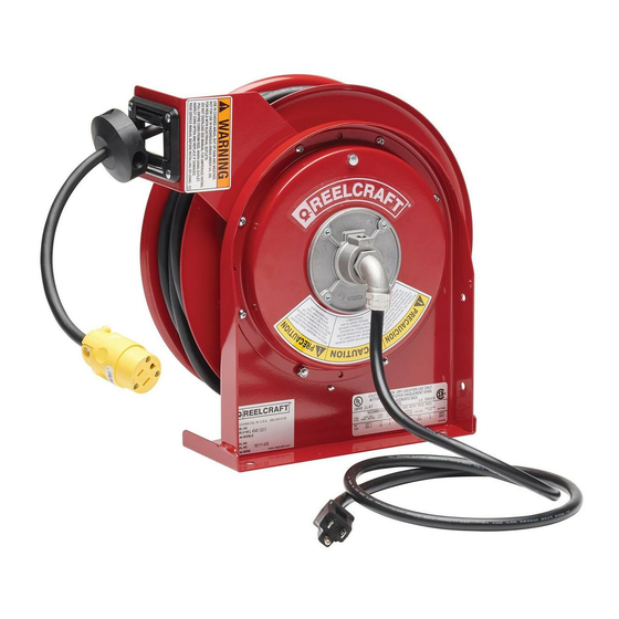
Heavy Duty Cord Reels - Condensed Version
Cord / Cable Reels
Series L 4000
Series L NM400
Series L 5000
Series L 7000
Read these instructions carefully before attempting to install, operate or maintain
this product. Only qualified persons should install this product. Failure to comply
with instructions may result in personal injury and/or property damage. Every at-
tempt is made to ensure the accuracy and completion of these instructions; however,
manufacturer is not responsible for ommissions. To obtain the complete version of
service manuals, technical bulletins and support, please visit www.reelcraft.com or call
customer service during business hours.
Safety
1.
Ensure that power supply voltage does not
exceed maximum voltage rating of reel.
Also, ensure that reel is properly installed
before connecting to power supply.
2.
All cord reels with flying leads must be
hard wired to ensure proper function.
3.
Check for frayed/broken wires before each
use.
4.
Do not exeed maximum installation height
of 16 ft unless specified.
5.
A high tension spring assembly is con-
tained within the reel. Exercise extreme
caution.
6.
Remove all spring tension and electric
power before beginning any disassembly
process.
7.
If an electrical malfunction should occur,
remove power from reel immediately.
8.
Ensure that reel, electrical cord, and equip-
ment being serviced are properly grounded.
Use an ohmmeter to check ground continu-
ity.
9.
Reels that include explosion-proof fluores-
cent hand lamps are not explosion-proof
themselves.
10. The Ground Fault Circuit Interrupter Re-
ceptacle is designed to protect people from
line-to-ground shock hazards. The GCFI
does not protect against short circuits or
overloads. This is the function of the fuse
or circuit breaker. Test monthly.
11. Pull electrical cord from reel by grasping
the electrical cord itself, not the work de-
vice.
12. If reel ceases to unwind or rewind, remove
electrical power immediately. Do not jerk
excessively on electrical cable!
Reelcraft Industries, Inc. • 2842 E Business Hwy 30, Columbia City, IN 46725
Ph: 800-444-3134 / 260-248-8188 • Fax: 800-444-4587 / 260-248-2605
Customer Service: 855-634-9109 • reelcraft@reelcraft.com • www.reelcraft.com
Series L 70000
13. Treat and respect the cord reel as any other
piece of machinery, observing all common
safety practices.
Installation
Ensure that only a qualified electrician installs/
services this equipment. Observe applicable
NEC, OSHA, and local electrical codes when in-
stalling this equipment. Installation of GFCI cord
reels should be performed by a qualified and
licensed professional in accordance with local
building codes and applicable NEC standards.
Mounting & Guide Arm Adjustment
The cord reel is equipped for universal mount-
ing so that it can be mounted on a structurally
sound floor, wall or ceiling; whichever provides
maximum performance. The guide arm must be
rotated to a position that allows the cord to feed
through the roller brackets with minimal bend-
ing. Replace the fasteners. Where applicable,
the U-Bolt must be placed in the proper location
when rotating the guide arm, otherwise the reel
might "latch out" during use. Refer to online
manual for proper U-Bolt locations.
Lubrication
Cord reel spring and bearings are factory
lubricated and require no further lubrication.
Install/Replace the Cord
CAUTION: Exercise extreme caution when add-
ing or removing spring tension. Ensure reel
base is fastened down prior to adjusting
tension. Do not move spool while tightening
hose or latch will disengage.
1.
Wind spool flange required number of turns
to achieve proper tension (Refer to online
Tech Bulletin). Do not over-tighten.
Series L 4000
Series L NM400
2. Engage cord latching mechanism.
Remove access cover.
3.
Strip 4" to 8" of output electrical cord outer
jacket.
4.
Route cord through U-Bolt*, cutout in
spool, then through strain relief (90°
elbow). Tighten U-Bolt* and strain relief
(90° elbow) as required. *Where applicable;
not all models contain a U-bolt.
5.
Using wire nuts, connect output electrical
cord wires to collector assembly brush
wires. Connect ground wire of output elec-
trical cable to ground lug.
6.
Check for ground faults using an ohm-
meter.
7.
Install access cover. Carefully release latch
and firmly hold the cord while winding it
onto reel. Install bumper stop at desired
position.
Spring Tension Adjustments
To adjust spring tension, add or remove wraps
of cord from the spool, one wrap at a time, until
desired tension is obtained (refer to safety
cautionary statements). Cord latching
mechanism can be removed for constant tension
applications.
Repairs
Extensive repairs should be performed only by
the factory service center to avoid damage which
may cause serious injury or void your warranty.
CAUTION: Remove all spring tension and
electrical power before disassembly process.
Series L 5000
Series L 7000
& L 70000
Form #1213-109 Rev: 5/2018
Publicidad

Resumen de contenidos para Reelcraft L 4000 Serie
- Página 1 Tech Bulletin). Do not over-tighten. Form #1213-109 Rev: 5/2018 Reelcraft Industries, Inc. • 2842 E Business Hwy 30, Columbia City, IN 46725 Ph: 800-444-3134 / 260-248-8188 • Fax: 800-444-4587 / 260-248-2605 Customer Service: 855-634-9109 • reelcraft@reelcraft.com • www.reelcraft.com...
- Página 2 No sacuda excesivamente el cable eléctrico. Form #1213-109 Rev: 5/2018 Reelcraft Industries, Inc. • 2842 E Business Hwy 30, Columbia City, IN 46725 Ph: 800-444-3134 / 260-248-8188 • Fax: 800-444-4587 / 260-248-2605 Customer Service: 855-634-9109 • reelcraft@reelcraft.com • www.reelcraft.com...
- Página 3 Form #1213-109 Rev: 5/2018 Reelcraft Industries, Inc. • 2842 E Business Hwy 30, Columbia City, IN 46725 Ph: 800-444-3134 / 260-248-8188 • Fax: 800-444-4587 / 260-248-2605 Customer Service: 855-634-9109 • reelcraft@reelcraft.com • www.reelcraft.com...
- Página 4 Form #1213-109 Rev: 5/2018 Reelcraft Industries, Inc. • 2842 E Business Hwy 30, Columbia City, IN 46725 Ph: 800-444-3134 / 260-248-8188 • Fax: 800-444-4587 / 260-248-2605 Customer Service: 855-634-9109 • reelcraft@reelcraft.com • www.reelcraft.com...


