Shure Microflex MX300 Serie Guia Del Usuario
Ocultar thumbs
Ver también para Microflex MX300 Serie:
- Guia del usuario (41 páginas) ,
- Manual del usuario (29 páginas) ,
- Guia del usuario (25 páginas)
Tabla de contenido
Publicidad
Idiomas disponibles
Idiomas disponibles
Enlaces rápidos
GENERAL
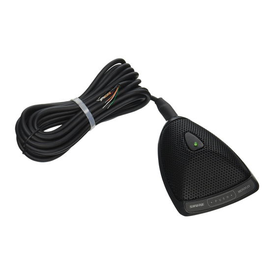
Shure Microflex MX300 Series microphones are surface-
mounted electret condenser microphones designed primarily
for mounting on conference tables, stage floors, and lecterns.
Their high sensitivity and wide frequency range make them
especially suitable for picking up speech and vocals in sound
reinforcement and recording applications. Interchangeable
cartridges provide the installer with greater flexibility and make
it possible to easily reconfigure microphone coverage as the
need arises. The MX392 and MX393 models include an inter-
nal preamplifier.
MX300 Series microphones take advantage of the princi-
ple that, at a barrier or boundary, the sound pressure level
doubles. When placed near a sufficiently large boundary
surface, the microphone has 6 dB higher sensitivity and ap-
proximately 3 dB greater direct-to-reverberant sound ratio.
FEATURES
Flat frequency response across the vocal range for
uncolored sound
Interchangeable cardioid, supercardioid, and omnidi-
rectional cartridges that provide choices for applications
Sleek, low-profile design for unobtrusive appearance
Balanced transformerless output for increased immunity
to noise over long cable runs
Low susceptibility to electromagnetic hum and RFI
Programmable on/off switch and LED on/off indicator
Logic input/output terminals for remote control or use with
automatic mixers (MX392 models only)
Application
Sound reinforcement for
speech and vocals
Recording or remote moni-
toring of speech and vocals
Video conferencing or
computer telephony
2000, Shure Incorporated
27C2834 (TJ)
MICROPHONE APPLICATION AND SELECTION GUIDE
Mounting Surface
Lectern, pulpit, stage floor, or
conference table
Lectern, pulpit, stage floor, or
conference table
Lecturn, pulpit, stage floor, or
conference table
Microflex MX300 Series User Guide
MODEL VARIATIONS
MX392 Models:
cludes a programmable membrane on/off switch, log-
ic input/output terminals, an on/off indicator LED,
screw
terminal
unterminated cable.
MX393 Models:
cludes a programmable membrane on/off switch, an
on/off indicator LED, and a Switchcraft Tini Q-G
connector.
Selecting a Cartridge
All Microflex microphones are available with any one of
three interchangeable cartridges. The polar pattern of the
original cartridge used in a particular microphone is
indicated by the model number suffix:
C = Cardioid, S = Supercardioid, O= Omnidirectional
Cardioid (C). Recommended for general sound rein-
forcement applications. Pickup angle (–3 dB) = 130 .
Supercardioid (S). Recommended for sound reinforce-
ment applications requiring narrow or more distant cover-
age. Pickup angle (–3 dB) = 115 .
Omnidirectional (O). Recommended for recording or
remote monitoring applications. Pickup angle (–3 dB) =
360 .
MICROPHONE PLACEMENT
To maintain the flattest possible low-frequency re-
sponse and optimum rejection of background noise, place
the microphone on a flat surface that is as large as pos-
sible. The surface can be a floor, table, or lectern.
NOTE: Avoid locating microphones near reflective sur-
faces other than the boundary surface (i.e., beveled sides
of pulpits or overhanging shelves). Failure to do so will re-
sult in increased levels of reverberant sound.
Microphone to
Cable Output
Cable Connector
Connector
Hard Wired
Hard Wired
Hard Wired
Hard Wired
Tini Q-G
Tini Q-G
Hard Wired
Hard Wired
Tini Q-G
Hardwired
Tini Q-G
Boundary Microphones
Surface-mount microphone; in-
connections,
Surface-mount microphone; in-
Polar Pattern
Cardioid
Supercardioid
XLR
Cardioid
XLR
Supercardioid
Omnidirectional
XLR
Omnidirectional
Cardioid
and
attached
Microflex
Model
MX392/C
MX392/S
MX393/C
MX393/S
MX392/O
MX393/O
MX392/CZ
Printed in U.S.A.
Publicidad
Tabla de contenido

Manuales relacionados para Shure Microflex MX300 Serie


Resumen de contenidos para Shure Microflex MX300 Serie
- Página 1 GENERAL indicated by the model number suffix: Shure Microflex MX300 Series microphones are surface- C = Cardioid, S = Supercardioid, O= Omnidirectional mounted electret condenser microphones designed primarily Cardioid (C). Recommended for general sound rein- for mounting on conference tables, stage floors, and lecterns.
- Página 2 SECURING MICROPHONES TO A MOUNTING SURFACE 12. Reconnect the wire leads to the screw terminals. (FIGURE 1) 13. Use fine sandpaper to remove any paint that may have adhered to the bottom edges of the grille. 1. Remove the Phillips screw from the bottom of the micro- phone base, then remove the retainer.
- Página 3 INTERNAL DIP SWITCH FUNCTIONS (FIGURE 5) MX392 LOGIC MODIFICATIONS To gain access to the logic terminals, remove the grille re- All MX392 and MX393 models have internal DIP switches tainer screw, the grille retainer, foam screen, and grille, as that allow the user to program the On/Off switch so that it fits shown in Figure 2.
-
Página 4: Replacement Parts
For additional techni- cal assistance, phone Shure at (847) 866-2200. In Europe, phone 49-7131-72140. SHURE, the Shure logo, and MICROFLEX are registered trade- marks of Shure Incorporated. Tini Q-G is a registered trademarks of Switchcraft Incorporated. -
Página 5: Placement Du Microphone
à membrane marche/arrêt, bor- GÉNÉRALITÉS nes d’entrée/sortie logique, témoin marche/arrêt, connec- Les Shure Microflex série MX300 sont des microphones teur à vis et câble fixe sans connecteur. électrostatiques à électret, à montage en surface, conçus Modèles MX393 : Microphone à montage en surface avec principalement pour les tables de conférence, planchers de... - Página 6 FIXATION DES MICROPHONES SUR UNE SURFACE 11. Sur le modèle MX392, faire un noeud simple sur le câ- DE MONTAGE (FIGURE 1) ble, aussi près que possible de l’extrémité de la gaine. Remettre le soulagement de contrainte en caoutchouc 1. Retirer la vis Phillips du bas de la base du microphone en place, dans le trou de sortie du câble.
-
Página 7: Fonction De Microphone Désirée
FONCTIONS DU COMMUTATEUR À POSITIONS MODIFICATIONS DE LOGIQUE DU MX392 MULTIPLES INTERNE (FIGURE 5) Pour accéder aux bornes de logique, retirer la vis de rete- nue de la grille, la retenue, l’écran de mousse et la grille, Tous les modèles MX392 et MX393 sont dotés d’un com- comme illustré... -
Página 8: Pièces De Rechange
Rejet en mode commun composer le 1–800–488–3297 et suivre les instructions de l’en- 45 dB minimum, 10 à 100 kHz registrement. Pour toute assistance technique supplémentaire, appeler Shure au (847) 866–2200. En Europe, appeler le Atténuation commutée 49–7131–72140. 50 dB au minimum... - Página 9 GRENZFLÄCHENMIKROFONE DER REIHE MX300 Modell MX392: Oberflächenmontiertes Mikrofon; einschließ- ALLGEMEINES lich programmierbarem Ein/Aus-Folienschalter, Eingabe/Aus- Shure Microflex Mikrofone der Reihe MX300 sind ober- gabe-Logikanschlüssen, Ein/Aus-LED-Anzeige, Schraubklem- flächenmontierte Elektretkondensatormikrofone, die in er- menverbindungen und eingebautem unabgeschlossenem ster Linie zur Anbringung auf Konferenztischen, Bühnenbö- Kabel.
- Página 10 ANBRINGUNG VON MIKROFONEN AUF EINER 10. Bei Verwendung eines Modells MX392 das Kabel durch BEFESTIGUNGSFLÄCHE (ABBILDUNG 1) den Sockel und dann durch die Gummizugentlastung einführen. 1. Die Kreuzschlitzschraube von der Unterseite des Mikro- 11. Bei Verwendung eines Modells MX392 einen einfachen fonsockels abnehmen, dann den Haltebügel entfernen.
- Página 11 9. Den mitgelieferten runden Gummistopfen in die nicht VERÄNDERUNGEN DER MX392 LOGIK verwendete Kabelöffnung einsetzen. Die Grillsicherungsschraube, den Haltebügel, die Schaum- 10. Den Grill, die Schaumstoffabschirmung und den Halte- stoffabschirmung und den Grill, wie in Abbildung 2 darge- bügel wieder einbauen und mit der Kreuzschlitzschrau- stellt, entfernen, um Zugriff zu den Logikanschlußklemmen be festziehen.
-
Página 12: Technische Daten
1–800–488–3297 (nur innerhalb der USA), dabei Anleitungen mindestens 45 dB, 10 Hz bis 100 kHz des Anrufbeantworters befolgen. Weitere technische Unterstüt- Schalterdämpfung zung wird von Shure unter der Rufnummer ++1 (847) 866–2200 mindestens 50 dB geleistet. In Europa bitte ++49 (7131) 72140 anrufen. -
Página 13: Generalidades
GENERALIDADES da/salida lógica, LED indicador de encendido/apagado, bor- Los micrófonos Microflex serie MX300 de Shure son mi- nes de conexión con tornillos y cable conectado sin enchufe. crófonos de condensador de electreto que se montan en su- Modelos MX393: Micrófono de montaje en superficie;... -
Página 14: Fijacion De Microfonos A La Superficie De Montaje (Figura 1)
FIJACION DE MICROFONOS A LA SUPERFICIE DE 12. Vuelva a conectar los alambres conductores a los bor- MONTAJE (FIGURA 1) nes de tornillo. 1. Quite el tornillo Phillips de la parte inferior de la base del 13. Use lija fina para quitar la pintura que se haya adherido micrófono y después quite el retén. -
Página 15: Funciones De Los Interruptores Dip Internos (Figura 5)
FUNCIONES DE LOS INTERRUPTORES DIP Para aislar la tierra de circuitos lógicos de la tierra de INTERNOS (FIGURA 5) circuitos de audio Los modelos MX392 y MX393 tienen interruptores DIP in- 1. Saque el puente R40 de la parte superior de la tarjeta ternos que permiten al usuario programar la función del in- de circuitos. -
Página 16: Especificaciones
45 dB mínimo, 10 Hz a 100 kHz 1–800–488–3297 y siga las instrucciones dadas en la graba- Atenuación del interruptor ción. Para recibir soporte técnico adicional, llame a Shure al te- 50 dB mínimo léfono (847) 866–2200. En Europa, llame al 49–7131–72140. -
Página 17: Descrizione Generale
Modelli MX392: microfono da fissaggio ad una superficie; inclu- DESCRIZIONE GENERALE de un interruttore generale (On/Off) programmabile a membrana, I microfoni Shure Microflex serie MX300 sono microfoni a con- terminali logici di ingresso/uscita, un LED di segnalazione On/Off, collegamenti dei terminali ad avvitamento e un cavo senza termi- densatore con elettrete, da fissare a superfici, concepiti principal- nazione (collegato). -
Página 18: Verniciatura Del Microfono (Figura 2)
FISSAGGIO DEL MICROFONO AD UNA SUPERFICIE 12. Fissare nuovamente i conduttori ai terminali ad avvita- DI MONTAGGIO (FIGURA 1) mento. 1. Svitare la vite con testa a croce Phillips dalla parte infe- 13. Usare carta smeriglio fine per asportare qualsiasi trac- riore della base del microfono e togliere il ritegno. - Página 19 FUNZIONI DEGLI INTERRUTTORI DIP INTERNI Isolamento della massa logica dalla massa audio (FIGURA 5) 1. Togliere il ponticello R40 dalla parte superiore della Tutti i modelli MX392 e MX393 contengono degli interruttori DIP scheda di circuiti. interni che permettono di programmare l’interruttore generale (On/ 2.
-
Página 20: Dati Tecnici
Omnidirezionale: 76,5 dB Rumore di uscita equivalente (ponderato A) mero 1–800–488–3297 (solo negli USA) e seguire le istruzioni registrate. Per assistenza tecnica, rivolgersi alla Shure chia- Cardioide: 23,0 dB mando il numero USA (847) 866–2200. In Europa, chiamare il Supercardioide: 22,0 dB Omnidirezionale: 17,5 dB numero 0047–7131–72140. - Página 21 HOUSING LOGEMENT GEHÄUSE CAJA CARTRIDGE ALLOGGIAMENTO BRACKET CARTOUCHE SUPPORT KAPSEL BEFESTIGUNGSSCHELLE CARTUCHO ESCUADRA CARTUCCIA STAFFA TAPE RUBAN ADHÉSIF KLEBEBAND CINTA ADHESIVA NASTRO CARTRIDGE REPLACEMENT REMPLACEMENT DE LA CARTOUCHE AUSTAUSCH DER KAPSEL SUSTITUCION DE CARTUCHO SOSTITUZIONE DELLA CARTUCCIA FIGURE 3 FIGURE 3 ABBILDUNG 3 FIGURA 3 FIGURA 3...
- Página 22 MIC OUT LED IN SORTIE MICRO ENTRÉEE DEL MIKRO AUS BIANCA LED EIN ORANGE ORANGE ORANGE NARANJA SALIDA DE MICROFONO ENTRADA DE LED USCITA MICROFONO INGRESSO LED BLACK NOIR SCHWARZ NEGRO NERO – SWITCH OUT COUPURE WEISS BLANCA VERDE WHITE BLANC SCHALTER AUSCHALTER AUS ROUGE...
- Página 23 76.2 mm 41.2 mm (3 in.) (1.621 in.) 108.3 mm (4.263 in.) DIMENSIONS DIMENSIONS ABMESSUNGEN DIMENSIONES DIMENSIONI FIGURE 9 FIGURE 9 ABBILDUNG 9 FIGURA 9 FIGURA 9 SIDE 1 CÔTÉ 1 SEITE 1 LADO 1 LATO 1 SIDE 2 CÔTÉ 2 SEITE 2 LADO 2 LATO 2 MX392/MX393 CIRCUIT BOARD LEGEND LÉGENDE DU CIRCUIT IMPRIMÉ...
- Página 24 MX392/MX393 SCHEMATIC DIAGRAM SCHEMA DE PRINCIPE MX392/MX393 SHURE Incorporated Web Address: http://www.shure.com STROMLAUFPLAN FUR MX392/MX393 222 Hartrey Avenue, Evanston, IL 60202–3696, U.S.A. DIAGRAMA ESQUEMATICO DEL MX392/MX393 Phone: 847-866–2200 Fax: 847-866-2279 In Europe, Phone: 49-7131-72140 Fax: 49-7131-721414 SCHEMA CIRCUITALE DEI MODELLI MX392/MX393...