Tabla de contenido
Publicidad
Idiomas disponibles
Idiomas disponibles
Enlaces rápidos
5S6130_Al.print USA.qxp:5S5403
Operating Instructions & Parts Manual
Please read and save these instructions. Read carefully before attempting to assemble, install, operate or maintain the product described.
Protect yourself and others by observing all safety information. Failure to comply with instructions could result in personal injury and/or
property damage! Retain instructions for future reference.
Speedaire
Aluminum Air Cylinders
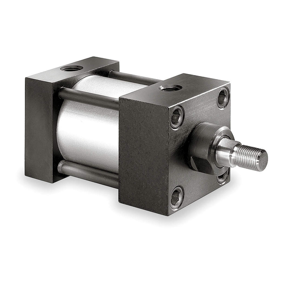
Description
Speedaire air cylinders are NFPA interchangeable. Heads and caps are
manufactured from solid aluminum bar stock. The tube is clear anodized on the
O.D. and hard anodic coated on the I.D. Piston rod is machined from hard chrome
plated, ground and polished steel. Removable bushing is sintered iron for
resistance to sideload. Mounting kits can be added without disturbing tie-rods.
8", 10" & 12" stoke cylinders are supplied with adjustable cushions on head and
cap to decelerate the load. Operating pressures to 250 psig air and 400 psig
hydraulic (non-shock).
Unpacking
Inspect cylinder carefully for any
damage occurring during transit. Check
for loose, missing or damaged parts.
Shipping damage claims must be filed
with the carrier.
Specifications
• Cylinders are rated to 250 psi air and
400 psi hydraulic (non-shock).
• Operating temperature range: -40°
to 200°F (-40° to 93°C).
1
• 1
/
" thru 6" bore cylinders are
2
supplied with a magnetic piston as
standard which facilitates the use of
position sensing switches, if required.
• Models with 8, 10 and 12 inch strokes
are equipped with adjustable
cushions.
General Safety Information
• Remove port plugs before
attempting to pressurize the cylinder.
• Keep hands and clothing away from
the air cylinder during operation.
• Do not exceed the pressure rating of
any component in the system.
• Protect airlines connected to the
cylinder from damage or puncture.
• Check airlines for weak or worn
conditions on a periodic basis and
before each use; making certain all
connections are secure
pressure prior to
cylinder disassembly!
Form 5S6130
9/6/08
5:35 PM
Page 1
®
Assembly
All cylinders are shipped fully
assembled. Mounting kits require
attachment to the cylinder using four
screws, included in the kit. Mounting
attachment instructions are shown
below for each mounting kit and rod
clevis.
MOUNTS
SIDE LUG MOUNT (STOCK NOS.
1A254 THRU 1A259)
Attach one side lug plate to the head
and one to the cap of the cylinder using
screws provided. Tapped holes are
machined in the head and cap for this
purpose. The tapped holes may also be
used for flush mounting the cylinder to
a flat surface.
FRONT / REAR FLANGE MOUNT
(STOCK NOS. 6X470, 6X472, 6X474,
6X478, 6X480 AND 1AO16)
NOTE: Eight (8) screws are provided
with each kit. (4) long and (4) short.
Front Flange – Secure rectangular
mounting flange to the head (rod end)
of the cylinder using (4) long screws.
The mounting screws pilot into the
internal threads of (4) sleeve nuts
located in the cylinder head.
Rear Flange – Secure rectangular
mounting flange to the cap of the
cylinder using (4) short screws. The
mounting screws thread into (4) tapped
holes located in the cylinder cap.
Remove all system
2W489A thru 2W493A, 6X370A thru
6X400A and 6X467A thru 6X469A
Large Bore
Printed in USA
02418
0808/306/VCPVP
REAR CLEVIS MOUNT (STOCK NOS.
6X471, 6X473, 6X475, 6X479, 6X481
AND 1A017)
Fasten the rear clevis mount to the cap
using the (4) screws provided.
Mounting screws thread into (4) tapped
holes located in the cylinder cap. Rear
Clevis Mount is supplied with a pivot pin.
ROD CLEVIS (STOCK NOS. 6X476,
6X482, AND 1A018)
Grip the piston rod using wrench flats
while threading the Rod Clevis onto
threads of piston rod. Rod Clevis is
supplied with a pivot pin.
EYE BRACKET (STOCK NOS. 6X477,
6X483 AND 1A019)
Eye Brackets are used as a mounting
accessory with Rear Clevis Mount or
Rod Clevis. (4) thru holes in each corner
of the Eye Bracket provide a means of
mounting the Eye Bracket to a flat
surface. The single eye of the bracket
mates with the double ears of either
the Rear Clevis Mount or Rod Clevis.
Align holes in both components and
insert pivot pin. NOTE: Eye Brackets are
not supplied with a pivot pin.
Installation
• To prolong cylinder life the use of a
filter, regulator and lubricator is
recommended.
• Proper alignment of the piston rod in
relationship to the load being moved
is essential for trouble-free operation.
• Eliminate any binding of the piston
rod over the full length of both the
extension and retraction stroke.
• Use Teflon tape or pipe thread
sealant to ensure leak-proof
connections.
• Do not scar or deform the surface of
the chrome-plated piston rod. Use
the wrench flats when attaching
accessories to the piston rod.
E
N
G
L
I
S
H
E
S
P
A
Ñ
O
L
F
R
A
N
Ç
A
I
S
Publicidad
Tabla de contenido

Manuales relacionados para Speedaire 2W489A thru

Resumen de contenidos para Speedaire 2W489A thru
- Página 1 REAR CLEVIS MOUNT (STOCK NOS. Description 6X471, 6X473, 6X475, 6X479, 6X481 Speedaire air cylinders are NFPA interchangeable. Heads and caps are AND 1A017) manufactured from solid aluminum bar stock. The tube is clear anodized on the O.D. and hard anodic coated on the I.D. Piston rod is machined from hard chrome Fasten the rear clevis mount to the cap plated, ground and polished steel.
- Página 2 5S6130_Al.print USA.qxp:5S5403 9/6/08 5:35 PM Page 2...
- Página 3 5S6130_Al.print USA.qxp:5S5403 9/6/08 5:35 PM Page 3...
-
Página 4: Troubleshooting Chart
5S6130_Al.print USA.qxp:5S5403 9/6/08 5:35 PM Page 4 2W489A thru 2W493A, 6X370A thru Speedaire Operating Instructions and Parts Manual 6X400A and 6X467A thru 6X469A Speedaire Large Bore Aluminum Air Cylinders ® Operation PISTON SEAL REPAIR: 8. Replace cylinder head by centering... -
Página 5: Descripción
® Descripción MONTADURA DE HORQUILLA Los cilindros de aire Speedaire son intercambiables con los aprobados por la National TRASERA (NÚMEROS 6X471, 6X473, Fluid Power Association (Asociación Nacional de Fuerza Fuída). Las cabezas y las tapas 6X475, 6X479, 6X481, Y 1A017) son fabricadas usando aluminio sólido en barras. - Página 6 5S6130_Al.print USA.qxp:5S5403 9/6/08 5:36 PM Page 6 Ñ...
- Página 7 5S6130_Al.print USA.qxp:5S5403 9/6/08 5:36 PM Page 7 Ñ...
-
Página 8: Cilindros Neumaticos De Aluminio Speedaire De Gran Diametro
9/6/08 5:36 PM Page 8 2W489A a 2W493A, 6X370A a Manual de Instrucciones de Operación y Lista de Partes 6X400A y 6X467A a 6X469A Cilindros neumaticos de aluminio Speedaire ® ® de gran diametro Operación REFACCIÓN DEL SELLO DEL 8. Reemplace la cabeza del cilindro centrándola sobre la barra del pistón y... - Página 9 (4) manchons taraudés situés dans la tête du cylindre. Les cylindres à air Speedaire sont aux normes de la National Fluid Power Association (Association national de transmissions Hydrauliques). Les têtes et les plaques d'extrémité sont Plaque arrière - Fixer la plaque de montage fabriquées à...
- Página 10 5S6130_Al.print USA.qxp:5S5403 9/6/08 5:36 PM Page 10 Ç...
- Página 11 5S6130_Al.print USA.qxp:5S5403 9/6/08 5:36 PM Page 11 Ç...
- Página 12 Page 12 2W489A à 2W493A, 6X370A à Manuel d'utilisation et de pièces détachées 6X400A et 6X467A à 6X469A Cylindres à air à alésage large Speedaire ® Installation REMPLACEMENT DU RACCORD DE TIGE: Insérer le piston et l'assemblage de la tige dans le tube.
- Página 13 Limitation of Liability. To the extent allowable under applicable law, Speedaire's liability for consequential and incidental damages is expressly disclaimed. Speedaire's liability in all events is limited to and shall not exceed the purchase price paid.
-
Página 14: Garantía Limitada
Renuncia a la Garantía. Speedaire se ha esforzado en describir e ilustrar sus productos con exactitud en éste manual; sin embargo, éstas descripciones e ilustraciones se hacen con el solo propósito de describir los productos y la compañía no garantiza que los productos aquí... -
Página 15: Garantie Limitée
Bien que Speedaire s'attache à ce que ses produits soient conformes aux normes, cette conformité ne peut être garantie et Speedaire ne sera en aucun cas tenu responsable de l'installation et de l'utilisation de l'appareil. Avant l'achat et l'utilisation du produit, examiner ses applications et les codes nationaux et locaux pour connaître la législation et pour s'assurer que le produit et son installation y... - Página 16 5S6130_Al.print USA.qxp:5S5403 9/6/08 5:36 PM Page 16 Speedaire Operating Instructions and Parts Manual Manual de Instrucciones de Operación y Lista de Partes Manuel d'utilisation et de pièces détachées Notes Ñ Ç Manufactured for / Fabricado para / Fabriqué pour Dayton Electric Mfg. Co.,...