Publicidad
Enlaces rápidos
Lumark
LVL20UG
ENGLISH
ITEMS REQUIRED
(Purchase separately)
• Phillips screwdriver
• Flat head screwdriver
• Mounting screws
• Weatherproof silicone caulk
IMPORTANT SAFETY INSTRUCTIONS
When using product, basic precautions should always be followed, including the following:
• Heed all warnings, including below warnings AND those included on product
NOTE: Failure to follow instructions may result in improper operation or void the warranty.
WARNING
• Read and follow these instructions
• cULus Listed for wet location use
• Disconnect at fuse or circuit breaker before installing or servicing
• Edges may cut. Handle with care
CAUTION
• Connect fixture to a 120 - 277V, 60 Hz power source. Any other connection voids
the warranty
• Fixture should be installed by persons with experience in household wiring or by a
qualified electrician. The electrical system, and the method of electrically connecting
the fixture to it, must be in accordance with the National Electrical Code and local
building codes
• For wall or ceiling mount application
• FOR SUPPLY CONNECTIONS, USE WIRE RATED FOR AT LEAST 75°C
• This device complies with Part 15 of the FCC Rules. Operation is subject to the
following two conditions: (1) This device may not cause harmful interference, and (2)
this device must accept any interference received, including interference that may cause
undesired operation
WARNING: FCC Regulations state that any unauthorized
changes or modifications to this equipment not expressly
approved by the manufacturer could void the user's
authorization to operate this equipment.
SAVE THESE INSTRUCTIONS AND WARNINGS
WARNING: Risk of electric shock. Disconnect power at fuse or
circuit breaker before installing or servicing.
NOTE: Make certain that the fixture is connected to a 120 - 277V universal power source.
UL-approved wire connectors should be used. Be sure no loose strands of wire are sticking
out from under your wire connectors.
Questions?/ Des questions?/ ¿Preguntas? 1-800-334-6871 ConsumerProducts@cooperlighting.com
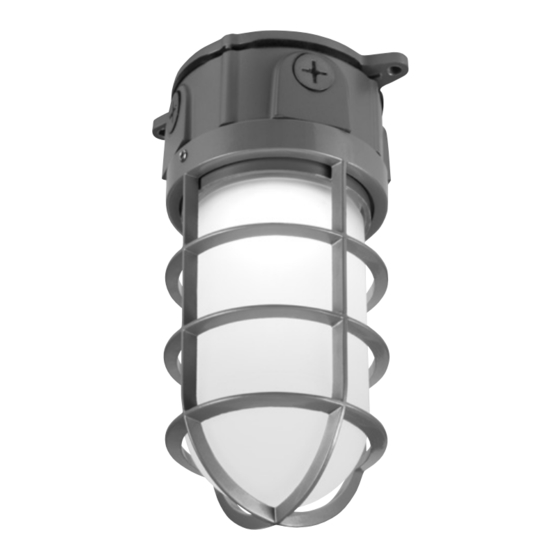
PACKAGING CONTENTS/ CONTENIDO DEL PAQUETE/ CONTENU DE L'EMBALLAGE
A. Fixture housing
Luminaria
Boîtier du luminaire
B. Guard
Protección
Protecteur
C. Glass lens
Lente de vidrio
Lentille en verre
Instruction Manual/Manuel d'instructions/ Instrucciones
D. Wire Connectors
Raccords de fils
Conectores del cable
INSTALLATION
1. This fixture can be installed directly to a flat surface
or as a pendant with a 1/2 inch conduit fitting.
Splice connections can be made inside the fixture
housing. To gain access to the fixture housing
remove fixture back plate by removing the 4
#6 - 32 screws on the back plate (Fig. 1).
2. To wire the fixture connect the white supply wire to
the white fixture wire using the included wire nut.
Connect the black supply wire to the black fixture
wire using included wire nut. Connect the supply
ground wire to the fixture ground wire using
included wire nut.
3. If using the fixture housing for splice connections
replace the fixture back plate using the Qty 4
#6 - 32 stainless steel screws (Fig. 3).
4. Mount housing to either 1/2 in. hanging conduit
or to a surface using the two tabs and mounting
screws (sold separately).
5. Apply silicone caulk around the base of the housing
or around the conduit to provide a watertight seal
against rain and moisture.
NOTE: If you remove one of the 4 conduit plugs and use
an alternate conduit location add thread sealing tape to
plug to ensure water tight seal in new plug location.
Ensure any unused conduit opening has a conduit plug.
CARE AND MAINTENANCE
1. Turn off power at main fuse or circuit breaker
before installing or servicing.
2. Loosen wire guard set screw using M2 allen
wrench.
3. Rotate wire guard counter clockwise to remove wire
guard (B) (Fig. 2).
4. Rotate lens counter clockwise to remove glass
lens (C).
5. Remove any dirt/debri from lens and clean lens with
glass cleaner or soap and water.
6. Remove any water/residue from lens with dry cloth.
7. Replace glass lens.
8. Replace wire guard.
9. Tighten wire guard set screw.
NOTE: If lens is replaced, use only tempered safety
glass of equal thickness per UL requirements.
1
Fig. 1
Fig. 2
1/2 inch threaded
conduit openings
Guard
set
screw
Fig. 3
3. Remove
glass lens
1. Remove
set screw
2. Remove
wire guard
Publicidad

Manuales relacionados para Cooper Lighting LUMARK LVL20UG


Resumen de contenidos para Cooper Lighting LUMARK LVL20UG
- Página 1 Lumark Instruction Manual/Manuel d’instructions/ Instrucciones Questions?/ Des questions?/ ¿Preguntas? 1-800-334-6871 ConsumerProducts@cooperlighting.com PACKAGING CONTENTS/ CONTENIDO DEL PAQUETE/ CONTENU DE L’EMBALLAGE A. Fixture housing D. Wire Connectors Luminaria Raccords de fils Boîtier du luminaire Conectores del cable B. Guard Protección Protecteur LVL20UG C.
- Página 2 ANY WARRANTY OF MERCHANTABILITY OR FITNESS FOR ANY PARTICULAR PURPOSE. expressément approuvée par le fabricant peut annuler le droit de Cooper Lighting Solutions ("CLS") warrants to customers that, for a period of five years from l’utilisateur à faire fonctionner cet équipement.
- Página 3 PARTICULIER. conexión eléctrica del portalámparas debe cumplir con el Código eléctrico nacional Cooper Lighting Solutions ("CLS") garantit à ses clients, pendant une période de cinq ans à y los códigos locales sobre edificios. compter de la date d’achat, que ses produits CLS sont exempts de tout défaut de matériaux et •...
- Página 4 SEAN IMPLÍCITAS, EXPLÍCITAS O ESTATUTARIAS, INCLUIDAS ENTRE OTRAS, LAS GARANTÍAS DE COMERCIABILIDAD E IDONEIDAD PARA UN FIN PARTICULAR. Cooper Lighting Solutions ("CLS") garantiza a sus clientes que los productos de CLS no presentarán defectos en los materiales y en la fabricación durante un período de cinco años desde la fecha de compra.