Publicidad
Enlaces rápidos
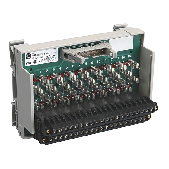
Fusible Interface Module
Module d'interface à fusible
Schnittstellenmodul mit Sicherung
Modulo di interfaccia con fusibili
Módulo de interface con fusible
(Cat 1492-IFM20F-F24A-2, -RIFM20F-F24A-2, -IFM20F-F120A-2, -RIFM20F-F120A-2)
WARNING
AVERTISSEMENT
WARNUNG
AVVERTENZA
ADVERTENCIA
Fuse Clips and Blown Fuse Indicators: See page 3 for fuse installation/removal.
Porte-fusibles et voyants de fusibles grillés: voir page 3 l'installation et le retrait des fusibles.
Sicherungshalterungen und Anzeige einer durchgebrannten Sicherung. Ein-und Ausbau der Sicherung siehe Seite 3.
Morsetti dei fusibili e indicatori dei fusibili bruciati: vedere il montaggio/smontaggio dei fusibili a pagina 3.
Sujetadores de fusibles e indicadores de fusible fundido: Vea la página 3 para obtener información sobre la instalación/extracción de fusibles.
= Connector Pin
= Broche de connexion
= Steckerstift
= Pin del connettore
= Pasador de conector
PN-23246
DIR 40063-280 (Version 09)
Printed in U.S.A.
To prevent electrical shock, disconnect from power source before installing or servicing. FM Class 1, Div.2 requires
device installation in a tool-accessible enclosure compliant with ANSI/ISA S82.
Avant le montage et la mise en service, couper l'alimentation secteur pour éviter toutes décharges. FM Classe 1, Div. 2
nécessite l'installation de l'équipement dans une armoire accessible aux interventions, conforme à ANSI/ISA S82.
Vor Installations- oder Servicearbeiten Strom-versorgung unterbrechen, um Elektroschocks zu vermeiden. FM-Klasse 1,
Gruppe 2 erfordert die Installation des Gerätes in einem Gehäuse, das für Werkzeuge zugänglich ist und den
Anforderungen gemäß ANSI/ISA S82 entspricht.
Per prevenire infortuni, togliere tensione prima dell'installazione o manutenzione. FM Classe 1, Divisione 2 richiede
l'installazione del dispositivo in un alloggiamento con capacità di accesso per strumenti conforme allo standard
ANSI/ISA S82.
Desconéctese de la corriente eléctrica, antes de la instalación o del servicio, a fin de impedir sacudidas eléctricas. El
requisito de FM (Factory Mutual) Clase 1, Div. 2, establece que el dispositivo debe instalarse en un envolvente que
permita la introducción y uso de herramientas y cumpla con la norma ANSI/ISA S82.
Module Identification Area.
Identification du module.
Modulkennzeichnungsbereich
Area per l'identificazione del modulo
Area de identificación del módulo.
20
(IFM40...)
2
(IFM20...)
19
1
1492-EAJ35
35 mm DIN Rail
199-DR1
199-DR4
1492-DR7
1 Adhesive Label Card. Provides terminal wiring identification and LED labels.
Carte étiquette adhésive. Identifie le câblage des bornes et les étiquettes des LED.
Aufklebbare Etiketten zur Kennzeichnung der Klemmenverdrahtung und LED-Anzeigen.
Scheda etichette adesive. Fornisce l'identificazione del cablaggio dei terminali e le etichette LED.
Tarjeta de etiquetas adhesivas. Proporciona identificación de cableado del terminal y etiquetas para los indicadores LED.
= Field-side Terminals
= Borne exterieure
= Feldseitiger Terminal
= Terminale lato-campo
= Terminal de campo
Lower = A
Upper = B
1
Publicidad

Manuales relacionados para Rockwell Automation Allen-Bradley 1492-IFM20F-F24A-2


Resumen de contenidos para Rockwell Automation Allen-Bradley 1492-IFM20F-F24A-2
- Página 1 Fusible Interface Module Module d’interface à fusible Schnittstellenmodul mit Sicherung Modulo di interfaccia con fusibili Módulo de interface con fusible (Cat 1492-IFM20F-F24A-2, -RIFM20F-F24A-2, -IFM20F-F120A-2, -RIFM20F-F120A-2) To prevent electrical shock, disconnect from power source before installing or servicing. FM Class 1, Div.2 requires WARNING device installation in a tool-accessible enclosure compliant with ANSI/ISA S82.
- Página 2 Module Remvable Terminal Block Installation / Removal Installation / Removal Montage / Retrait Montage / Retrait Installation / Entfernen Installation / Entfernen Montaggio / Smontaggio Montaggio / Smontaggio 1492-N90 1492-N90 Instalación / Extracción Instalación / Extracción 3.5-4.5 lb-in (0.38-0.50 Nm) 0.32 in 0.32 in (8 mm)
- Página 3 Pinout 1492-IFM20F-F24A-2 Brochage 1492-RIFM20F-F24A-2 1492-IFM20F-F120A-2 Anschlußbelegung 1492-RIFM20F-F120A-2 Disposizione dei piedini Esquema de pins Blown Fuse Indicator Circuit Circuit du voyant de rupture de fusible Anzeigeschaltung für durchgebrannte Sicherung Indicatore dei fusibili bruciati Circuito del indicador de fusible fundido Fuse Installation/Removal Installation/retrait des fusibles Ein- und Ausbau der Sicherung Montaggio/smontaggio dei fusibili...
- Página 4 I/O Wiring Data Wiring information for your I/O module, AIFM module and cable (e.g. wiring diagram and pinouts)are available online at www.rockwellautomation.com/en/e-tools. NOTICE To obtain information follow this procedure. 1) In the Catalog Number BOX at the above online site type in the catalog number of the IFM, AIFM, etc. module you are using and click on Submit. 2) At the next screen displayed, click on the Modify key (lower left of screen).