Publicidad
Enlaces rápidos
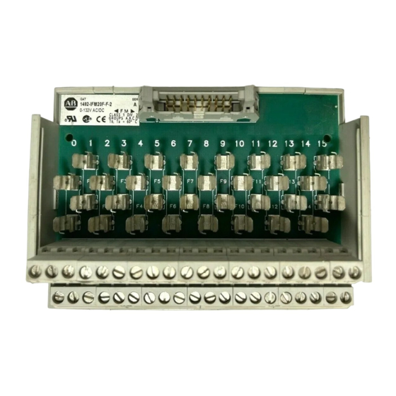
Fusible Interface Modules
Modules d'interface à fusibles
Schnittstellenmodule mit Sicherung
Moduli di interfaccia con fusibili
Módulos de interface con fusible
(Cat 1492-IFM20F-F-2, -RIFM20F-F-2, -IFM20F-F24-2, -RIFM20F-F24-2, -IFM20F-F120-2, -RIFM20F-F120-2, -IFM20F-F240-2,
-IFM20F-F24A-2, -RIFM20F-F24A-2, -IFM20F-F120A-2, -RIFM20F-F120A-2, -IFM40F-F-2, -IFM40F-F24-2, -RIFM40F-F24-2, -IFM40F-F120-2)
WARNING
AVERTISSEMENT
WARNUNG
AVVERTENZA
ADVERTENCIA
Fuse Clips and Blown Fuse Indicators: See page 4 for fuse installation/removal.
Porte-fusibles et voyants de fusibles grillés: voir page 4 l'installation et le retrait des fusibles.
Sicherungshalterungen und Anzeige einer durchgebrannten Sicherung. Ein-und Ausbau der Sicherung siehe Seite 4.
Morsetti dei fusibili e indicatori dei fusibili bruciati: vedere il montaggio/smontaggio dei fusibili a pagina 4.
Sujetadores de fusibles e indicadores de fusible fundido: Vea la página 4 para obtener información sobre la instalación/extracción de fusibles.
= Connector Pin
= Broche de connexion
= Steckerstift
= Pin del connettore
= Pasador de conector
2
1
Screw Row "B"
Screw Row "A"
Terminal "B" Row
Wire
Terminal "A" Row
Wire
PN-264488
DIR 10001268600 (Version 01)
Printed in U.S.A.
To prevent electrical shock, disconnect from power source before installing or servicing. FM Class 1, Div.2 requires device installation in a
tool-accessible enclosure compliant with ANSI/ISA S82.
Pour éviter le risque d'électrocution, débranchez la source d'alimentation avant l'installation ou l'entretien. En classe 1, division 2, le dispositif
doit être installé dans une enceinte adaptée à l'environnement et accessible uniquement à l'aide d'un outil (selon ANSI/ISA S82).
Zum Schutz gegen elektrischen Schlag, trennen Sie das Gerät von der Stromquelle, bevor Sie es installieren oder Wartungsarbeiten
durchführen. Für Klasse 1, Div 2 sollten Sie das Gerät in einem für das Umfeld geeigneten Gehäuse installieren, das nur unter
Verwendung eines Werkszeugs (gemäß ANSI/ISA S82) zugänglich ist.
Para evitar choques elétricos, desligue a alimentação antes de instalar ou executar manutenção. Para a Classe 1, Div 2, o dispositivo
se deve instalar em um invólucro adequado ao ambiente. O invólucro deve permitir acesso somente mediante a utilização de f
erramentas (segundo ANSI/ISA S82).
Para evitar choques eléctricos, desconecte el dispositivo de la fuente de alimentación eléctrica antes de instalar o prestar servicio.
Para la Clase 1, Div 2, el dispositivo se debe instalar en un envolvente adecuado para el entorno. Dicho envolvente debe permitir acceso
solamente con la ayuda de una herramienta (según ANSI/ISA S82).
(IFM20...)
20
40
(IFM40...)
19
(IFM20...)
39
(IFM40...)
35 mm DIN Rail
199-DR1
199-DR4
1492-DR7
A1
B1
Adhesive Label Card. Provides terminal wiring identification.
Carte étiquette adhésive. Identifie le câblage des bornes.
Aufklebbare Etiketten zur Kennzeichnung der Klemmenverdrahtung.
Scheda etichette adesive. Fornisce l'identificazione del cablaggio
dei terminali.
Tarjeta de etiquetas adhesivas. Proporciona identificación de cableado
del terminal.
= Field-side Terminals
= Borne exterieure
= Feldseitiger Terminal
= Terminale lato-campo
= Terminal de campo
Upper = B
Lower = A
Publicidad

Manuales relacionados para Rockwell Automation 1492-IFM20F-F-2


Resumen de contenidos para Rockwell Automation 1492-IFM20F-F-2
- Página 1 Schnittstellenmodule mit Sicherung Moduli di interfaccia con fusibili Módulos de interface con fusible (Cat 1492-IFM20F-F-2, -RIFM20F-F-2, -IFM20F-F24-2, -RIFM20F-F24-2, -IFM20F-F120-2, -RIFM20F-F120-2, -IFM20F-F240-2, -IFM20F-F24A-2, -RIFM20F-F24A-2, -IFM20F-F120A-2, -RIFM20F-F120A-2, -IFM40F-F-2, -IFM40F-F24-2, -RIFM40F-F24-2, -IFM40F-F120-2) WARNING To prevent electrical shock, disconnect from power source before installing or servicing. FM Class 1, Div.2 requires device installation in a tool-accessible enclosure compliant with ANSI/ISA S82.
-
Página 2: Technische Daten
Peso aproximado al momento de Referencia Rango de temperatura de funcionamient Humedad operativa embarque Width Height Depth 1492-IFM20F-F-2 0.76 lb (344 g.) 4.33 in (110mm) 1492-RIFM20F-F-2 0.76 lb (344 g.) 4.33 in (110mm) 1492-IFM20F-F24-2 0.76 lb (344 g.) 4.33 in (110mm) 1492-RIFM20F-F24-2 0.76 lb (344 g.) - Página 3 Fuse Installation / Removal Installation / retrait des fusibles 5 x 20 mm (max 2.0A per circuit; 12A per module) Ein- und Ausbau der Sicherung 5 x 20 mm (max 2,0A par circuit; 12A par module) 5 x 20 mm (max 2,0A pro Stromkreis; 12A pro Modul) Montaggio / smontaggio dei fusibili 5 x 20 mm (max 2,0A per circuito;...
- Página 4 Matrice des câbles Kabelmatrix Matrice cavi Matriz de cables I/O Module Catalog No. Module E/S Référence E/A-Modul Bestell-Nr. 1492-IFM20F-F120-2 1492-IFM20F-F240-2 1492-IFM20F-F24A-2 1492-IFM20F-F120A-2 1492-IFM20F-F24-2 1492-IFM20F-F-2 N. Catalogo Modulo I/O 1492-RIFM20F-F-2 1492-RIFM20F-F24-2 1492-RIFM20F-F120-2 1492-RIFM20F-F24A-2 1492-RIFM20F-F120A-2 Referencia Módulo de E/S 1746-IA16 1492-CABLE 1746-IB16 1492-CABLE...
- Página 5 Pinout Brochage Anschlußbelegung Disposizione dei piedini Esquema de pins 1492-IFM20F-F-2 1492-RIFM20F-F-2 1492-IFM20F-F24-2 1492-RIFM20F-F24-2 1492-IFM20F-F120-2 1492-IFM20F-F240-2 1492-RIFM20F-F120-2 = Connector Pin = Broche de connexion = Steckerstift 1492-IFM20F-F24-2 = Pin del connettore 1492-RIFM20F-F24-2 = Pasador de conector 1492-IFM20F-F240-2 (ONLY) Blown Fuse Indicator Circuit...
- Página 6 Max. Intensidad/módulo Referencia Max. Intensidad/circuito de indicadores Voltaje de cresta iterativo máximo Code at 60°C Voltaje 1492-IFM20F-F-2 0 - 132 V AC/DC 1492-RIFM20F-F-2 0 - 132 V AC/DC 1492-IFM20F-F24-2 10 - 30 V AC/DC 2.0 mA 2 Amps 12 Amps...