Publicidad
Idiomas disponibles
Idiomas disponibles
Please read these instructions carefully before installing, operating, or servicing the fan. Retain this guide for future reference.
WARNING
TO REDUCE THE RISK OF FIRE, ELECTRIC
SHOCK, OR INJURY TO PERSONS, OBSERVE
THE FOLLOWING:
1. Use this unit only in the manner intended
by the manufacturer. If you have questions,
contact the manufacturer at the address or
telephone number listed in the warranty.
2. Before servicing or cleaning unit, switch
power off at service panel and lock the service
disconnecting means to prevent power from
being switched on accidentally. When the
service disconnecting means cannot be
locked, securely fasten a prominent warning
device, such as a tag, to the service panel.
3. Installation work and electrical wiring must be
done by a qualified person(s) in accordance
with all applicable codes and standards,
including fire-rated construction codes and
standards.
4. Sufficient air is needed for proper combustion
and exhausting of gases through the flue
(chimney) of fuel burning equipment to
prevent backdrafting. Follow the heating
equipment manufacturer's guideline and
safety standards such as those published
by the National Fire Protection Association
(NFPA), and the American Society for
Heating, Refrigeration and Air Conditioning
Engineers (ASHRAE), and the local code
authorities.
5. When cutting or drilling into wall or ceiling, do
not damage electrical wiring and other hidden
utilities.
6. Ducted fans must always be vented to the
outdoors.
7. This unit must be grounded.
8. To reduce risk of fire, use only metal ductwork.
9. The electric service supply voltage must be
120V 60HZ.
WIRING DIAGRAM
AUTOMATIC TERMINAL SWITCH
CAUTION
1. For general ventilating use only. Do not use
to exhaust hazardous or explosive materials
and vapors.
2. To avoid motor bearing damage and noisy
and/or unbalanced impellers, keep drywall
spray, construction dust, etc. off power unit.
3. Please read specification label on product for
further information and requirements.
4. Do not use in the bathroom.
5. To reduce the risk of injury, install fan at least
2.1m (7 feet) above the floor.
SERVICE PARTS
1. Grille
2. Sheet Metal Nut
3. Sheet Metal Screws
4. Motor Mounting Bracket
5. Motor
6. Blade
7. Wiring Box Cover
8. Green Ground Screw
9. Wiring Box
FAN HOUSING
10. Housing
11. Receptacle
12. Spring
13. Adjustable Duct
14. Wall Cap
15. Aluminum Ring
14
15
13
TO 120V/60HZ
JUNCTION BOX
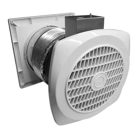
BV-WF-01-LV WALL FAN
Installation Guide
USE AND CARE
WARNING: Switch off power at service panel and
lock service panel before cleaning or servicing
this fan.
TO CLEAN FAN ASSEMBLY:
Unplug motor from receptacle. Remove the motor
assembly by loosening the mounting screws and
rotating the motor assembly.
Gently vacuum motor assembly and inside of
housing.
METAL AND ELECTRICAL PARTS SHOULD
NEVER BE IMMERSED IN WATER.
PERIODCALLY CHECK THE OUTER LOUVER
FOR ACCUMULATED
WHICH MAY INTERFERE WITH PROPER
LOUVER CLOSURE.
WARNING: DO NOT SPRAY WATER INTO
LOUVER—DAMAGE TO THE FAN COULD
OCCUR AND WATER COULD ENTER HOUSE.
There is no need to oil the motor on this fan.
9
8
7
11
3
6
12
10
BLACK WIRE
WHITE WIRE
GREEN WIRE
DUST,
LINT,
ETC.,
1
4
5
3
2
3
1
Publicidad
Tabla de contenido

Manuales relacionados para BV BV-WF-01-LV

Resumen de contenidos para BV BV-WF-01-LV
- Página 1 BV-WF-01-LV WALL FAN Installation Guide Please read these instructions carefully before installing, operating, or servicing the fan. Retain this guide for future reference. WARNING CAUTION USE AND CARE TO REDUCE THE RISK OF FIRE, ELECTRIC 1. For general ventilating use only. Do not use...
- Página 2 INSTALLATION NOTE: Fan can be installed in outside walls up to 10″ thick. Walls less than 6″ thick will not use the adjustable duct. Choose a location with no obstructions. Fan can be operated by a wall switch or speed control (available separately). WARNING: When cutting or drilling into wall, do not cut existing electrical wiring.
- Página 3 (For walls 6″ to 10″ thick only—including inside and outside wall coverings.) Stretch the adjustable duct, slide it over the housing and tape it in place (non-tapered end of flexible duct may need to be shortened to fit). TAPE HERE Position fan housing in wall.
- Página 4 Reinstall electrical wiring box and cover. Reinstall motor assembly (if previously removed). Plug the fan motor into receptacle on wiring box cover. (Complete this step only if adjustable duct is used.) From outside, slip adjustable duct into the aluminum ring attached to the wall cap and tape the joint.
- Página 5 LIMITED WARRANTY This is a quality product. It was made with care, and BV offers a limited one-year warranty against any manufacturing defects as long as it has been used as directed. BV will replace any product showing such manufacturing defects. This warranty does not include labor costs for the installation or removal of...
-
Página 6: Repuestos Y Mantenimiento
BV-WF-01-LV VENTILADOR DE PARED Guía de Instalación Porfavor, lea estas instrucciones detenidamente antes de instalar, operar o reparar el ventilador. Conserve esta guía para futura referencia. ADVERTENCIA PRECAUCIÓN USO Y CUIDADO PARA REDUCIR EL RIESGO DE INCENDIO, 1. Solo para ventilación general. No lo use para ADVERTENCIA: Apague la energia en el panel DESCARGA ELÉCTRICA O LESIONES A LAS... -
Página 7: Instalación
INSTALACIÓN NOTA: El ventilador se puede instalar en paredes exteriores de hasta 10 “de grosor. Las paredes de menos de 6 ″ de grosor no utilizarán el conducto ajustable. Elija un lugar sin obstrucciones. El ventilador puede ser operado por un interruptor de pared o control de velocidad (disponible por separado). - Página 8 (Solo para paredes de 6 ″ a 10 ″ de grosor, incluidos los revestimientos de paredes interiores y exteriores.) Estire el conducto ajustable, deslícelo sobre el alojamiento y péguelo con cinta adhesiva en su lugar (es posible que sea necesario acortar el extremo no cónico del conducto flexible).
- Página 9 Vuelva a instalar la caja de cableado eléctrico y cobertor. Vuelva a instalar el conjunto del motor (si se retiró anteriormente). Enchufe el motor del ventilador en el receptáculo de la cubierta de la caja de cableado. (Complete este paso solo si se utiliza un conducto ajustable.) Desde el exterior, deslice el conducto ajustable dentro del anillo de amluminio unido a la tapa de...
-
Página 10: Garantía Limitada
GARANTÍA LIMITADA Este es un producto de calidad. Fue hecho con cuidado, y BV ofrece una garantía limitada de un año contra cualquier defecto de fabricación, siempre que se haya utilizado según las instrucciones. BV reemplazará cualquier producto que muestre tales defectos de fabricación. Esta garantía no incluye los...