Tabla de contenido
Publicidad
Idiomas disponibles
Idiomas disponibles
Enlaces rápidos
Harbor Breeze® is a registered trademark
of LF, LLC. All Rights Reserved.
Purchase Date
Questions, problems, missing parts? Before returning to your retailer, call our customer
service department at 1-800-643-0067, 8 a.m. - 8 p.m., EST, Monday - Sunday.
VR20320
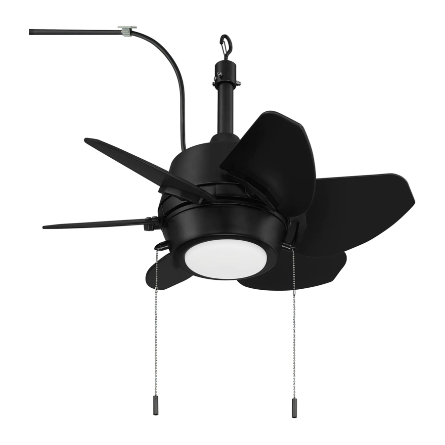
GASKIN CEILING FAN
1
ITEM #2599783
MODEL #GAT24BNK6L
Español p. 19
ATTACH YOUR RECEIPT HERE
ADJUNTE SU RECIBO AQUÍ
4007498
Publicidad
Capítulos
Tabla de contenido
Solución de problemas

Manuales relacionados para LF Harbor Breeze GAT24BNK6L

Resumen de contenidos para LF Harbor Breeze GAT24BNK6L
- Página 1 ITEM #2599783 GASKIN CEILING FAN MODEL #GAT24BNK6L Harbor Breeze® is a registered trademark of LF, LLC. All Rights Reserved. Español p. 19 ATTACH YOUR RECEIPT HERE ADJUNTE SU RECIBO AQUÍ 4007498 Purchase Date Questions, problems, missing parts? Before returning to your retailer, call our customer service department at 1-800-643-0067, 8 a.m.
-
Página 2: Tabla De Contenido
TABLE OF CONTENTS Safety Information .........................2 Package Contents .........................5 Hardware Contents .......................6 Preparation ..........................6 Initial Installation ........................6 Wiring ...........................10 Final Installation ........................12 Operating Instructions .......................15 Care and Maintenance ......................17 Troubleshooting........................17 Limited Lifetime Warranty ....................18 Replacement Parts List .......................18 SAFETY INFORMATION Modifications not approved by the party responsible for compliance could void the user's authority to operate the equipment. - Página 3 SAFETY INFORMATION READ AND SAVE THESE INSTRUCTIONS Please read and understand this entire manual before attempting to assemble, install or operate the product. • Do not discard fan carton or foam inserts. Should this fan need to be returned to the factory for repairs, it must be shipped in its original packaging to ensure proper protection against damage that might exceed the initial cause for return.
- Página 4 SAFETY INFORMATION WARNING WARNING To reduce the risk of fire or electrical shock, do not use the fan with any solid state speed control device or control fan speed with a full range dimmer switch. To reduce the risk of fire, electrical shock or personal injury, do not bend the blades when installing or balancing them or cleaning the fan.
-
Página 5: Package Contents
PACKAGE CONTENTS PART DESCRIPTION PART DESCRIPTION QUANTITY QUANTITY Downrod Canopy Mounting Screw (preassembled) Canopy Pin (preassembled) Mounting Bracket Clip (preassembled) Motor Housing Blade Arm Yoke Cover Switch Housing Screw LED Light Kit (preassembled) Blade Motor Plate Screw Switch Housing (preassembled) Shade Motor Screw/Lock Washer Canopy Cover... -
Página 6: Hardware Contents
HARDWARE CONTENTS (shown actual size) Fiber Blade Wire Blade Screw Connector Washer Pull Chain Qty. 18 Qty. 3 Qty. 18 Extension + 1 extra + 1 extra Qty. 2 PREPARATION Before beginning assembly of product, make sure all parts are present. Place motor on carpet or on foam to avoid damage to finish. -
Página 7: Important
INITIAL INSTALLATION Determine mounting method to use. A. Standard mount B. Angle mount IMPORTANT: If using the angle mount, ensure the ceiling angle is not steeper than 19°. NOTE: Closemount option is not available for this fan. 19° max. *Helpful Hint: Downrod-style mounting is best suited for ceilings 8 ft. - Página 8 INITIAL INSTALLATION 5. Remove preassembled motor screws/lock washers (Q) from underside of motor housing (D). If there are plastic motor blocks installed with the motor screws/lock washers (Q), discard the plastic motor blocks. Note: Make sure to keep loose hardware separate Plastic to avoid confusion during installation.
- Página 9 INITIAL INSTALLATION 8. Slip downrod (A) into motor housing yoke, align holes and re-install pin (L) and clip (M). Tighten set screws in motor housing yoke and then tighten preassembled nut on one of the set screws. Then, slide yoke cover (E) down until it rests on top of motor housing (D).
-
Página 10: Wiring
INITIAL INSTALLATION 11. Install hanging ball of downrod (A) into opening of mounting bracket (C). Align one of the slots in hanging ball with tab in mounting bracket (C). DANGER: Failure to align one of the slots in the ball with the tab may result in serious injury or death. - Página 11 WIRING 1b. FAN CONTROLLED BY PULL CHAIN, LIGHT FAN CONTROLLED BY PULL CHAIN, LIGHT BY WALL SWITCH BY WALL SWITCH: Connect BLACK wire from fan to BLACK wire from ceiling. Connect BLUE wire from fan to the BLACK wire from the independent 120V POWER FROM CEILING wall switch for the light.
-
Página 12: Final Installation
FINAL INSTALLATION Locate two canopy mounting screws (K) on underside of mounting bracket (C) and remove canopy mounting screw (K) closest to the open end of the mounting bracket (C). Partially loosen the other canopy mounting screw (K). Lift canopy (B) to mounting bracket (C). - Página 13 FINAL INSTALLATION 4. Remove one motor plate screw (P) from motor plate preassembled on the underside of the motor housing (D) and partially loosen the other two motor plate screws (P). Align slotted holes in switch housing (H) with loosened motor plate screws (P), allowing molex connections from Motor motor housing (D) to come through hole in switch...
- Página 14 FINAL INSTALLATION 7. Connect male plug from motor housing (D) to female plug from switch housing (H), matching up the colors on the male plug with the colors on the female plug for correct fit. Make sure plugs are connected completely.
-
Página 15: Operating Instructions
FINAL INSTALLATION Attach pull chain extensions (DD) or custom pull chain extensions (not included) to fan and light pull chains. Hardware Used Pull Chain Extension OPERATING INSTRUCTIONS The fan pull chain, located to the left of the reverse switch, has four positions to control fan speed. - Página 16 OPERATING INSTRUCTIONS Use the fan reverse switch on the switch housing (H) to optimize your fan for seasonal performance. A ceiling fan will allow you to raise your thermostat setting in summer and lower your thermostat setting in winter without feeling a difference in your comfort.
-
Página 17: Care And Maintenance
CARE AND MAINTENANCE At least twice each year, lower canopy (B) to check downrod (A) assembly, and then tighten all screws on fan. Clean motor housing (D) with only a soft brush or lint-free cloth to avoid scratching the finish. Clean blades (G) with a lint-free cloth. You may occasionally apply a light coat of furniture polish to wood blades for added protection. -
Página 18: Limited Lifetime Warranty
TROUBLESHOOTING PROBLEM POSSIBLE CAUSE CORRECTIVE ACTION [Fan operates but 2. Wall switch to fan is off. 2. Make sure that wall switch to fan is light fails.] 3. Wires in LED light kit not wired 3. Check that molex connections in correctly. -
Página 19: Ventilador De Techo Gaskin
VENTILADOR DE TECHO GASKIN MODELO #GAT24BNK6L Harbor Breeze® es una marca registrada de LF, LLC. Todos los derechos reservados. ADJUNTE SU RECIBO AQUÍ 4007498 Fecha de compra ¿Preguntas, problemas, piezas faltantes? Antes de volver a la tienda, llame a nuestro Departamento de Servicio al Cliente al 1-800-643-0067, de lunes a domingo de 8 a. - Página 20 ÍNDICE Información de seguridad .......................20 Contenido del paquete ......................23 Lista de aditamentos ......................24 Preparación ..........................24 Instalación inicial ........................24 Cableado ..........................28 Instalación final........................29 Instrucciones de funcionamiento ....................33 Cuidado y mantenimiento .......................35 Solución de problemas ......................35 Garantía limitada de por vida ....................36 Lista de piezas de repuesto ....................36 INFORMACIÓN DE SEGURIDAD Las modificaciones que no estén aprobadas por la parte responsable del cumplimiento podrían...
- Página 21 INFORMACIÓN DE SEGURIDAD LEA Y GUARDE ESTAS INSTRUCCIONES • No deseche la caja del ventilador ni los accesorios de espuma. En caso de que deba devolver este ventilador a la fábrica para realizarle reparaciones, se debe enviar en su embalaje original para asegurar una protección adecuada contra daños que puedan aumentar la causa inicial de la devolución.
-
Página 22: Información De Seguridad
INFORMACIÓN DE SEGURIDAD ADVERTENCIA Para reducir el riesgo de incendios o descargas eléctricas, no use el ventilador con dispositivos de control de velocidad para ventiladores de estado sólido ni controle la velocidad del ventilador con un regulador de intensidad de rango completo. Para reducir el riesgo de incendio, descargas eléctricas o lesiones personales, no doble las aspas al instalarlas, equilibrarlas o al limpiar el ventilador. -
Página 23: Contenido Del Paquete
CONTENIDO DEL PAQUETE PIEZA DESCRIPCIÓN CANTIDAD PIEZA DESCRIPCIÓN CANTIDAD Varilla Tornillo de montaje de la base (preensamblado) Base Pasador (preensamblado) Soporte de montaje Sujetador (preensamblado) Carcasa del motor Brazo del aspa Cubierta de la horquilla Tornillo de la carcasa del Kit de iluminación LED interruptor (preensamblado) Aspa... -
Página 24: Preparación
ADITAMENTOS (se muestran en tamaño real) Arandela Tornillo Conector para aspa para aspa de cables de fibra Extensión para la Cant. 18 Cant. 3 Cant. 18 cadena de tiro más 1 más 1 adicional adicional Cant. 2 PREPARACIÓN Antes de comenzar a ensamblar el producto, asegúrese de tener todas las piezas. Compare las piezas con la lista del contenido del paquete y la lista de aditamentos. - Página 25 INSTALACIÓN INICIAL 2. Determine el método de instalación que utilizará. A. Montaje estándar B. Montaje en ángulo IMPORTANTE: si realiza el montaje en ángulo, verifique que el ángulo del techo no tenga una inclinación superior a los 19°. Nota: las opciones de montaje cerrado y de montaje 19°...
- Página 26 INSTALACIÓN INICIAL 5. Retire los tornillos del motor/arandelas de seguridad (Q) preensamblados de la parte inferior de la carcasa del motor (D). Si hay topes plásticos del motor instalados con los tornillos del motor/arandelas de seguridad (Q), deseche los topes plásticos del motor. Tope plástico Nota: asegúrese de mantener todo el aditamento...
- Página 27 INSTALACIÓN INICIAL 8. Deslice la varilla (A) en la horquilla de la carcasa del motor, alinee los orificios y vuelva a instalar el pasador (L) y el sujetador (M). Apriete los tornillos de fijación en la horquilla de la carcasa del motor y apriete las tuercas previamente ensambladas a los tornillos de fijación.
-
Página 28: Cableado
INSTALACIÓN INICIAL Instale la bola para colgar en la varilla (A) en la abertura del soporte de montaje (C). Alinee una de las ranuras en la bola para colgar con la lengüeta del soporte de montaje (C). PELIGRO: si no alinea una de las ranuras de la bola con la lengüeta, podrían producirse lesiones graves o la muerte. -
Página 29: Cadena De Tiro Y Luz Controlada Por Interruptor De Pared
CABLEADO 1b. VENTILADOR CONTROLADO POR VENTILADOR CONTROLADO POR CADENA DE TIRO Y LUZ CONTROLADA POR INTERRUPTOR DE PARED CADENA DE TIRO Y LUZ CONTROLADA POR INTERRUPTOR DE PARED: conecte el cable NEGRO del ventilador al cable NEGRO del techo. ALIMENTACIÓN Conecte el cable AZUL del ventilador al cable DE 120 V DESDE EL TECHO... -
Página 30: Instalación Final
INSTALACIÓN FINAL Ubique dos tornillos de montaje de la base (K) debajo del soporte de montaje (C) y retire el tornillo de montaje de la base (K) más cercano al extremo abierto del soporte de montaje (C). Afloje parcialmente el otro tornillo de montaje de la base (K). - Página 31 INSTALACIÓN FINAL 4. Retire un tornillo de la placa del motor (P) preensamblado en la placa del motor en la parte inferior de la carcasa del motor (D) y afloje parcialmente los otros dos tornillos de la placa del motor (P). Alinee los orificios ranurados en la carcasa del interruptor (H) con los tornillos de la Placa del placa del motor (P) y permita que el enchufe...
- Página 32 INSTALACIÓN FINAL 7. Conecte el enchufe macho de la carcasa del motor (D) con el enchufe hembra de la carcasa del interruptor (H) y haga combinar los colores de los enchufes para que encastren correctamente. Asegúrese de que los enchufes estén firmemente conectados.
-
Página 33: Instrucciones De Funcionamiento
INSTALACIÓN FINAL Conecte las extensiones para la cadena de tiro (DD) o las extensiones para la cadena de tiro personalizadas (no incluidas) con las cadenas de tiro del ventilador y luz correspondientes. Aditamentos utilizados Extensión para la cadena de tiro INSTRUCCIONES DE FUNCIONAMIENTO La cadena de tiro del ventilador, ubicada a la izquierda del interruptor de reversa, tiene cuatro... - Página 34 INSTRUCCIONES DE FUNCIONAMIENTO Utilice el interruptor de reversa de la carcasa del interruptor (H) para optimizar el rendimiento de su ventilador según la estación del año. Un ventilador de techo le permitirá elevar la configuración de su termostato en verano y disminuirla en invierno, sin sentir una diferencia en su comodidad.
-
Página 35: Cuidado Y Mantenimiento
CUIDADO Y MANTENIMIENTO Al menos dos veces al año, baje la base (B) para revisar el ensamble de la varilla (A) y luego apriete todos los tornillos en el ventilador. Limpie la carcasa del motor (D) solo con un cepillo suave o un paño que no produzca pelusas para evitar rayar el acabado. -
Página 36: Garantía Limitada De Por Vida
SOLUCIÓN DE PROBLEMAS PROBLEMA CAUSA POSIBLE ACCIÓN CORRECTIVA [El ventilador 2. El interruptor de pared de la luz 2. Asegúrese de que el interruptor de pared de funciona pero la la luz esté en la posición de encendido. está apagado. luz no.] 3.