Tabla de contenido
Publicidad
Idiomas disponibles
Idiomas disponibles
Enlaces rápidos
WINDOWS, DOORS & LIGHTS
SMP301-11
Switch-mode power supply
EN
Installation and Operating Manual. . . . . . . . 5
Schaltnetzteil
DE
Montage- und Bedienungsanleitung . . . . . 16
Bloc d'alimentation
FR
Instructions de montage
et de service . . . . . . . . . . . . . . . . . . . . . . . . .27
Fuente conmutada
ES
Instrucciones de montaje y de uso . . . . . . .39
Alimentatore a commutazione
IT
Istruzioni di montaggio e d'uso . . . . . . . . .50
Voeding
NL
Montagehandleiding en
gebruiksaanwijzing . . . . . . . . . . . . . . . . . . .62
Koplingsstrømforsyning
NO
Monterings- og bruksanvisning . . . . . . . . .73
RV PRODUCTS
Publicidad
Capítulos
Tabla de contenido
Solución de problemas

Manuales relacionados para Dometic SMP 301-11


Resumen de contenidos para Dometic SMP 301-11
- Página 1 WINDOWS, DOORS & LIGHTS RV PRODUCTS SMP301-11 Switch-mode power supply Installation and Operating Manual..5 Schaltnetzteil Montage- und Bedienungsanleitung ..16 Bloc d'alimentation Instructions de montage et de service ......27 Fuente conmutada Instrucciones de montaje y de uso .
- Página 3 SMP301-11...
- Página 4 SMP301-11 ≥ 200 mm ≥ 50 mm ≥ 200 mm ≥ 200 mm ≥ 200 mm ≥ 100 mm...
-
Página 5: Tabla De Contenido
SMP301-11 Explanation of symbols Please read this instruction manual carefully before installation and first use, and store it in a safe place. If you pass on the product to another person, hand over this instruction manual along with it. Table of contents Explanation of symbols . -
Página 6: Safety Instructions
Safety instructions SMP301-11 NOTICE! Indicates a situation that, if not avoided, can result in property damage. NOTE Supplementary information for operating the product. Safety instructions The manufacturer accepts no liability for damage in the following cases: • Faulty assembly or connection •... -
Página 7: Operating The Product Safely
SMP301-11 Safety instructions • Take the precautions necessary to ensure that children cannot inter- fere with the product. Dangerous situations may occur which cannot be recognized by chil- dren! NOTICE! • Do not expose the product to any heat source (such as direct sunlight or heating). -
Página 8: Scope Of Delivery
Scope of delivery SMP301-11 Scope of delivery • Switch-mode power supply • Installation and operating manual Accessories Available as accessories (not included in the scope of delivery): Description Ref. no. Surge protector 9106505815 Intended use The SMP301-11 switch-mode power supply is suitable for installation in habitable recreational vehicles (caravans, motor caravans). -
Página 9: Product Overview
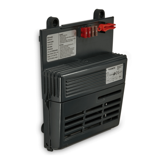
SMP301-11 Technical description Product overview Item in Element fig. 1, page 3 Mounting holes Fuse extractor Brackets for 4 spare fuses Clips for releasing of the cover Cover of the connection space Strain relief clamps AC connection Connections and displays Item in Element fig. -
Página 10: Installing The Switch-Mode Power Supply
Installing the switch-mode power supply SMP301-11 Installing the switch-mode power supply Fastening the switch-mode power supply When selecting the installation location, pay attention to the following instructions: • The switch-mode power supply must be installed vertically on a wall (maximum ambient temperature 50 °C) or horizontally on the ground or on a pedestal (max- imum ambient temperature 40 °C and maximum load 75 %). - Página 11 SMP301-11 Installing the switch-mode power supply ➤ Connect the negative terminal of the consumer unit to the flat plug (any pin) (fig. 2 10, page 3). ➤ Connect the AC connection cable to the AC connection (fig. 1 7, page 3). ➤...
-
Página 12: Using The Switch-Mode Power Supply
Using the switch-mode power supply SMP301-11 Switching via external 12 V switching voltage ➤ Make sure jumpers 6 (fig. 2 5, page 3) and 10 (fig. 2 8, page 3) are not set. ➤ Set jumper 9 (fig. 2 4, page 3). ✓... -
Página 13: Maintaining And Cleaning The Switch-Mode Power Supply
SMP301-11 Maintaining and cleaning the switch-mode power supply ➤ If the plug-in fuse is tripped again, please contact the manufacturer’s branch in your country (see the back of the instruction manual for the addresses) or your retailer. Using the surge protector (optional) The optional surge protector (ref. -
Página 14: Troubleshooting
Troubleshooting SMP301-11 Troubleshooting Fault Cause Repair Output is not The plug-in fuse of the output is defec- Replace the plug-in fuse with a tive. The red LED (fig. 4 1, page 4) is supplied. plug-in fuse of equivalent value. lit. The switch-mode power supply has The surge protector resets auto- switched off as a result of the surge... -
Página 15: Disposal
SMP301-11 Disposal Disposal ➤ Place the packaging material in the appropriate recycling waste bins wherever possible. If you wish to finally dispose of the product, ask your local recycling centre or specialist dealer for details about how to do this in accordance with the applicable disposal regulations. -
Página 16: Erläuterung Der Symbole
Erläuterung der Symbole SMP301-11 Bitte lesen Sie diese Anleitung vor Einbau und Inbetriebnahme sorgfältig durch und bewahren Sie sie auf. Geben Sie sie im Falle einer Weitergabe des Produktes an den Nutzer weiter. Inhaltsverzeichnis Erläuterung der Symbole ........16 Sicherheitshinweise . -
Página 17: Sicherheitshinweise
SMP301-11 Sicherheitshinweise ACHTUNG! Hinweis auf eine Situation, die zu Sachschäden führen kann, wenn sie nicht vermieden wird. HINWEIS Ergänzende Informationen zur Bedienung des Produktes. Sicherheitshinweise Der Hersteller übernimmt in folgenden Fällen keine Haftung für Schäden: • Montage- oder Anschlussfehler • Beschädigungen am Produkt durch mechanische Einflüsse und falsche Anschlussspannung •... - Página 18 Sicherheitshinweise SMP301-11 Sicherheit bei der Installation des Produkts WARNUNG! • Die elektrische Installation darf nur von einer Fachkraft nach den natio- nalen Vorschriften angeschlossen werden. Durch unsachgemäßes Anschließen können erhebliche Gefahren entstehen. • Sichern Sie das Produkt so, dass Kinder keinen Zugriff darauf haben. Es können Gefahren entstehen, die von Kindern nicht erkannt werden! ACHTUNG!
-
Página 19: Lieferumfang
SMP301-11 Lieferumfang • Unterbrechen Sie bei Arbeiten am Produkt immer die Strom- versorgung. ACHTUNG! • Achten Sie darauf, dass die Belüftungsschlitze des Produkts nicht ver- deckt werden. • Achten Sie auf gute Belüftung. Lieferumfang • Schaltnetzteil • Montage- und Bedienungsanleitung Zubehör Als Zubehör erhältlich (nicht im Lieferumfang enthalten): Bezeichnung... - Página 20 Technische Beschreibung SMP301-11 Das Schaltnetzteil kann auf drei Arten geschaltet werden: • über einen CI-Bus • über eine externe 12-V-Schaltspannung • über die Stromversorgung (Dauerbetrieb, solange Spannung anliegt) Geräteübersicht Pos. in Element Abb. 1, Seite 3 Befestigungslöcher Sicherungsheber Halterungen für 4 Ersatzsicherungen Laschen zum Lösen der Abdeckung Abdeckung des Anschlussraums Zugentlastungen...
-
Página 21: Schaltnetzteil Montieren
SMP301-11 Schaltnetzteil montieren Schaltnetzteil montieren Schaltnetzteil befestigen Beachten Sie bei der Wahl des Montageortes folgende Hinweise: • Das Schaltnetzteil darf senkrecht an einer Wand (maximale Umgebungs- temperatur 50 °C) oder waagerecht auf dem Boden oder einem Podest (maximale Umgebungstemperatur 40 °C und maximale Last 75 %) montiert werden. - Página 22 Schaltnetzteil montieren SMP301-11 ➤ Schließen Sie den Pluspol der Verbraucher an den Flachstecker (beliebiger Stift) (Abb. 2 9, Seite 3) an. ➤ Schließen Sie den Minuspol der Verbraucher an den Flachstecker (beliebiger Stift) (Abb. 2 10,Seite 3) an. ➤ Schließen Sie das Wechselstrom-Anschlusskabel an den Wechselstroman- schluss (Abb.
-
Página 23: Schaltnetzteil Benutzen
SMP301-11 Schaltnetzteil benutzen Über CI-Bus schalten ➤ Stellen Sie sicher, dass die Jumper 6 (Abb. 2 5, Seite 3) und 9 (Abb. 2 4, Seite 3) nicht gesetzt sind. ➤ Setzen Sie Jumper 10 (Abb. 2 8, Seite 3). ✓ Das Schaltnetzteil kann nun über den CI-Bus gesteuert werden. Über externe 12-V-Schaltspannung schalten ➤... -
Página 24: Schaltnetzteil Pflegen Und Reinigen
Schaltnetzteil pflegen und reinigen SMP301-11 ➤ Drücken Sie die beiden Laschen (Abb. 1 4, Seite 3) in Pfeilrichtung und heben Sie die Abdeckung (Abb. 1 5, Seite 3) ab. ➤ Ersetzen Sie die defekte Stecksicherung durch eine neue Stecksicherung des Typs „ATO Type –... -
Página 25: Fehlerbeseitigung
SMP301-11 Fehlerbeseitigung Fehlerbeseitigung Fehler Ursache Behebung Ausgang wird Die Stecksicherung des Ausgangs Ersetzen Sie die Stecksicherung ist defekt. Die rote LED (Abb. 4 1, nicht versorgt. durch eine gleichwertige Steck- Seite 4) leuchtet. sicherung. Das Schaltnetzteil hat durch den Der Überspannungsschutz setzt Überspannungsschutz sich automatisch zurück, wenn die abgeschaltet. -
Página 26: Entsorgung
Entsorgung SMP301-11 Entsorgung ➤ Geben Sie das Verpackungsmaterial möglichst in den entsprechenden Recycling-Müll. Wenn Sie das Produkt endgültig außer Betrieb nehmen, informieren Sie sich bitte beim nächsten Recyclingcenter oder bei Ihrem Fachhändler über die zutreffenden Entsorgungsvorschriften. Technische Daten SMP301-11 Art.-Nr.: 9106504722 Ausführung: mit Relais... -
Página 27: Signification Des Symboles
SMP301-11 Signification des symboles Veuillez lire attentivement cette notice avant le montage et la mise en service. Veuillez ensuite la conserver. En cas de passer le produit, veuillez le transmettre au nouvel acquéreur. Sommaire Signification des symboles ........27 Consignes de sécurité... -
Página 28: Consignes De Sécurité
Consignes de sécurité SMP301-11 AVIS ! Remarque signalant une situation qui peut entraîner des dommages matériels si elle n’est pas évitée. REMARQUE Informations complémentaires sur l'utilisation du produit. Consignes de sécurité Le fabricant décline toute responsabilité pour des dommages dans les cas suivants : •... - Página 29 SMP301-11 Consignes de sécurité Sécurité lors du montage du produit AVERTISSEMENT ! • Seul un électricien spécialisé est habilité à effectuer l'installation, en respectant les directives nationales. Tout raccordement incorrect ris- querait d'entraîner de graves dangers. • Conservez le produit hors de la portée des enfants. Il peut se produire des situations dangereuses qui ne peuvent pas être reconnues par les enfants.! AVIS !
-
Página 30: Contenu De La Livraison
Contenu de la livraison SMP301-11 AVIS ! • Assurez-vous que les fentes d'aération du produit ne sont pas cou- vertes. • Veillez à une bonne ventilation. Contenu de la livraison • Alimentation en mode de commutation • Instructions de montage et de service Accessoires Disponibles en accessoires (non compris dans la livraison) : Description... -
Página 31: Vue D'ensemble Du Produit
SMP301-11 Description technique L’alimentation en mode commutation peut être commutée de l'une des trois manières suivantes : • Via le bus CI • Via une tension de commutation externe de 12 V • Via l'alimentation électrique (fonctionnement continu tant que la tension est pré- sente) Vue d’ensemble du produit Position dans... -
Página 32: Installation De L'alimentation En Mode Commutation
Installation de l'alimentation en mode commutation SMP301-11 Position dans Élément fig. 2, page 3 Cavalier 10 (J10) – active le bus CI (si J9 n'est pas installé) Sortie connecteur plat (pôle positif) Sortie connecteur plat (pôle négatif) Installation de l'alimentation en mode commutation Fixation de l'alimentation en mode commutation Lors de la sélection de l'emplacement d'installation, faites attention aux instructions... - Página 33 SMP301-11 Installation de l'alimentation en mode commutation AVIS ! Avant de commencer à percer, assurez-vous qu’aucun câble électrique ou autre élément du véhicule ne risque d’être endommagé par le per- çage, le sciage ou le limage. Fixez l’alimentation en mode commutation de la manière suivante : ➤...
-
Página 34: Changement De Mode De Commutation
Installation de l'alimentation en mode commutation SMP301-11 Changement de mode de commutation REMARQUE Veillez à ce que les cavaliers 9 (fig. 2 4, page 3) et 10 (fig. 2 8, page 3) ne soient jamais activés en même temps. Si les deux cavaliers sont activés en même temps, les deux possibilités de commutation par le bus CI et par la tension de commutation 12 V externe sont bloquées. -
Página 35: Utilisation De L'alimentation En Mode Commutation
SMP301-11 Utilisation de l'alimentation en mode commutation Utilisation de l'alimentation en mode commutation L’alimentation en mode commutation s'enclenche dès qu’une alimentation élec- trique externe est disponible. Remplacement des fusibles enfichables Remplacez un fusible enfichable (fig. 2 2, page 3) grillé uniquement par un fusible enfichable de même valeur. -
Página 36: Entretien Et Nettoyage De L'alimentation En Mode Commutation
Entretien et nettoyage de l'alimentation en mode commutation SMP301-11 Entretien et nettoyage de l'alimentation en mode commutation AVIS ! N’utilisez aucun objet coupant ou dur pour le nettoyage de l’appareil. Cela risquerait de l’endommager. ➤ Débranchez l’alimentation en mode commutation de l’alimentation électrique. ➤... -
Página 37: Garantie
SMP301-11 Garantie Garantie Le délai légal de garantie s'applique. Si le produit s'avérait défectueux, veuillez vous adresser à la filiale du fabricant située dans votre pays (voir la dernière page) ou à votre revendeur spécialisé. Veuillez y joindre les documents suivants pour la gestion des réparations et de la garantie : •... -
Página 38: Caractéristiques Techniques
Caractéristiques techniques SMP301-11 Caractéristiques techniques SMP301-11 N° d’article : 9106504722 Version : avec relais Tension d'entrée nominale : 230 Vw (198 Vw à 264 Vw) Puissance de sortie continue : 350 W Tension de sortie : 24 Vg Intensité du courant : 17 A Température ambiante : –10 °C à... -
Página 39: Explicación De Los Símbolos
SMP301-11 Explicación de los símbolos Lea detenidamente estas instrucciones antes de llevar a cabo la instalación y puesta en funcionamiento, y consérvelas en un lugar seguro. En caso de vender o entregar el producto a otra persona, entregue también estas instrucciones. -
Página 40: Indicaciones De Seguridad
Indicaciones de seguridad SMP301-11 ¡AVISO! Aviso sobre una situación que, si no se evita, puede causar daños materiales. NOTA Información complementaria para el manejo del producto. Indicaciones de seguridad El fabricante declina toda responsabilidad ante daños ocurridos en los siguientes casos: •... -
Página 41: Seguridad Durante El Montaje Del Producto
SMP301-11 Indicaciones de seguridad Seguridad durante el montaje del producto ¡ADVERTENCIA! • La instalación eléctrica solo la puede efectuar personal técnico con- forme a las normas del país en cuestión. Una conexión realizada inco- rrectamente puede dar lugar a situaciones de considerable peligro. •... -
Página 42: Volumen De Entrega
Volumen de entrega SMP301-11 ¡AVISO! • Asegúrese de que las rejillas de ventilación del aparato no queden tapadas. • Garantice una buena ventilación. Volumen de entrega • Fuente conmutada • Instrucciones de montaje y uso Accesorios Disponibles como artículos opcionales (no incluidos en el volumen de entrega): Descripción N.°... -
Página 43: Vista General De Productos
SMP301-11 Descripción técnica La fuente conmutada se puede activar de una de estas tres formas: • Vía CI-bus • Vía tensión de activación externa de 12 V • Vía alimentación de tensión (funcionamiento continuo mientras haya tensión) Vista general de productos Elemento en la Elemento fig. -
Página 44: Instalación De La Fuente Conmutada
Instalación de la fuente conmutada SMP301-11 Instalación de la fuente conmutada Sujeción de la fuente conmutada Al elegir el lugar de montaje, preste atención a las siguientes indicaciones: • La fuente conmutada debe instalarse en vertical en una pared (temperatura ambiente máxima 50 °C) u horizontal en el suelo o un alza (temperatura ambiente máxima 40 °C y carga máxima 75 %). -
Página 45: Conexión Del Ci-Bus O De Un Interruptor Externo
SMP301-11 Instalación de la fuente conmutada ➤ Conecte el polo positivo de la unidad receptora a la clavija plana (cualquier pin) (fig. 2 9, página 3). ➤ Conecte el polo negativo de la unidad receptora a la clavija plana (cualquier pin) (fig. -
Página 46: Uso De La Fuente Conmutada
Uso de la fuente conmutada SMP301-11 Conmutación vía CI-bus ➤ Asegúrese de que los jumpers 6 (fig. 2 5, página 3) y 9 (fig. 2 4, página 3) no están ajustados. ➤ Ajuste el jumper 10 (fig. 2 8, página 3). ✓... -
Página 47: Uso De La Protección De Sobretensión (Opcional)
SMP301-11 Mantenimiento y limpieza de la fuente conmutada ➤ Presione ambos clips (fig. 1 4, página 3) en la dirección de las flechas y levante la cubierta (fig. 1 5, página 3). ➤ Sustituya los fusibles enchufables fundidos solo por fusibles enchufables nuevos del tipo “ATO Type –... -
Página 48: Resolución De Problemas
Resolución de problemas SMP301-11 Resolución de problemas Fallo Causa Reparación No se entrega El fusible enchufable de la salida está Sustituya el fusible enchufable averiado. El LED rojo (fig. 4 1, corriente. por un fusible enchufable del página 4) está iluminado. mismo valor. -
Página 49: Gestión De Residuos
SMP301-11 Gestión de residuos Gestión de residuos ➤ Deseche el material de embalaje en el contenedor de reciclaje correspondiente. Cuando vaya a desechar definitivamente el producto, infórmese en el centro de reciclaje más cercano o en un comercio especializado sobre las normas pertinentes de eliminación de materiales. -
Página 50: Spiegazione Dei Simboli
Spiegazione dei simboli SMP301-11 Prima di effettuare il montaggio e la messa in funzione leggere accurata- mente questo manuale di istruzioni, conservarlo e in caso di trasmissione del prodotto, consegnarlo all'utente successivo. Indice Spiegazione dei simboli ........50 Istruzioni per la sicurezza . -
Página 51: Istruzioni Per La Sicurezza
SMP301-11 Istruzioni per la sicurezza AVVISO! Indicazione di una situazione che se non evitata può provocare danni materiali. NOTA Informazioni integranti relative all'impiego del prodotto. Istruzioni per la sicurezza Il produttore non si assume nessuna responsabilità per danni nei seguenti casi: •... - Página 52 Istruzioni per la sicurezza SMP301-11 Sicurezza durante l’installazione del prodotto AVVERTENZA! • L’installazione elettrica deve essere collegata solo da personale quali- ficato conformemente alle prescrizioni nazionali. Un collegamento non eseguito correttamente può causare rischi enormi. • Prendere le precauzioni necessarie per garantire che i bambini non possano interferire con il prodotto.
-
Página 53: Dotazione
SMP301-11 Dotazione • Interrompere sempre l’alimentazione elettrica quando si opera sul prodotto. AVVISO! • Accertarsi che le griglie di ventilazione presenti nel prodotto non siano coperte. • Garantire una buona ventilazione. Dotazione • Alimentatore a commutazione • Istruzioni di montaggio e d’uso Accessori Disponibili come accessori (non in dotazione): Descrizione... - Página 54 Descrizione delle caratteristiche tecniche SMP301-11 Per l’alimentazione elettrica l’alimentatore a commutazione è collegato a una ten- sione di 230 V CA (capitolo “Collegamento dell’alimentatore a commutazione” a pagina 56). L’alimentatore a commutazione può essere acceso in uno dei tre modi seguenti: •...
-
Página 55: Montaggio Dell'alimentatore A Commutazione
SMP301-11 Montaggio dell’alimentatore a commutazione Posizione nella Elemento fig. 2, pagina 3 Ponticello 10 (J10) – attiva l’CI-bus (se J9 non è impostato) Spina piatta per uscita (polo positivo) Spina piatta per uscita (polo negativo) Montaggio dell’alimentatore a commutazione Fissaggio dell’alimentatore a commutazione Per la scelta del luogo di montaggio, osservare le seguenti indicazioni: •... - Página 56 Montaggio dell’alimentatore a commutazione SMP301-11 AVVISO! Prima di effettuare qualsiasi tipo di foro, assicurarsi che nessun cavo elet- trico o altri componenti del veicolo vengano danneggiati durante l’uso di trapani, seghe e lime. Fissare l’alimentatore a commutazione come segue: ➤ Serrare una vite in ognuno dei quattro fori di montaggio (fig. 1 1, pagina 3). Collegamento dell’alimentatore a commutazione ➤...
- Página 57 SMP301-11 Montaggio dell’alimentatore a commutazione Modifica della modalità di commutazione NOTA Assicurarsi che i ponticelli 9 (fig. 2 4, pagina 3) e 10 (fig. 2 8, pagina 3) non siano mai attivati allo stesso momento. Se entrambi i pon- ticelli sono attivati allo stesso momento, le due alternative di commuta- zione mediante CI-bus e mediante tensione di commutazione esterna a 12 V sono bloccate.
-
Página 58: Utilizzo Dell'alimentatore A Commutazione
Utilizzo dell’alimentatore a commutazione SMP301-11 Utilizzo dell’alimentatore a commutazione L’alimentatore a commutazione si attiva non appena è disponibile un’alimentazione elettrica esterna. Sostituzione dei fusibili a lama Sostituire un fusibile a lama bruciato (fig. 2 2, pagina 3) solo con un fusibile a lama equivalente. -
Página 59: Manutenzione E Pulizia Dell'alimentatore A Commutazione
SMP301-11 Manutenzione e pulizia dell’alimentatore a commutazione Manutenzione e pulizia dell’alimenta- tore a commutazione AVVISO! Per la pulizia non utilizzare oggetti appuntiti o ruvidi perché potrebbero provocare danni all’apparecchio. ➤ Staccare l’alimentatore a commutazione dalla tensione di alimentazione. ➤ Se necessario, pulire l’alimentatore a commutazione utilizzando un panno. Eliminazione dei guasti Guasto Causa... -
Página 60: Garanzia
Garanzia SMP301-11 Garanzia Vale il termine di garanzia previsto dalla legge. Qualora il prodotto risultasse difet- toso, La preghiamo di rivolgersi alla filiale del produttore del suo Paese (vedi retro), oppure al rivenditore specializzato di riferimento. Per la riparazione e per il disbrigo delle condizioni di garanzia è necessario inviare la seguente documentazione: •... -
Página 61: Specifiche Tecniche
SMP301-11 Specifiche tecniche Specifiche tecniche SMP301-11 N. art.: 9106504722 Versione: con relè Tensione nominale di 230 Vw (da 198 Vw a 264 Vw) ingresso: Potenza di uscita continua: 350 W Tensione di uscita: 24 Vg Intensità di corrente: 17 A Temperatura ambiente: da –10 °C a +40 °C Classe di protezione:... -
Página 62: Verklaring Van De Symbolen
Verklaring van de symbolen SMP301-11 Lees deze handleiding voor de montage en de ingebruikname zorgvuldig door en bewaar hem. Geef de handleiding bij het doorgeven van het product aan de gebruiker. Inhoudsopgave Verklaring van de symbolen ........62 Veiligheidsinstructies . -
Página 63: Veiligheidsinstructies
SMP301-11 Veiligheidsinstructies LET OP! Aanwijzing met betrekking tot een situatie die kan leiden tot materiële schade, als deze niet wordt vermeden. INSTRUCTIE Meer informatie over de bediening van het product. Veiligheidsinstructies De fabrikant kan in de volgende gevallen niet aansprakelijk worden gesteld voor schade: •... - Página 64 Veiligheidsinstructies SMP301-11 Veiligheid bij de montage van het product WAARSCHUWING! • De elektrische installatie mag alleen door een elektricien conform de nationale voorschriften worden aangesloten. Onjuiste aansluiting kan ernstige gevaren veroorzaken. • Neem de nodige voorzorgsmaatregelen om te voorkomen dat kinde- ren het product kunnen storen.
-
Página 65: Omvang Van De Levering
SMP301-11 Omvang van de levering LET OP! • Let erop dat de ventilatieopeningen van het product niet afgedekt worden. • Zorg voor goede ventilatie. Omvang van de levering • Schakelende voeding • Montage- en bedieningshandleiding Toebehoren Als toebehoren verkrijgbaar (niet inbegrepen in de omvang van de levering): Beschrijving Artikelnr. -
Página 66: Productoverzicht
Technische beschrijving SMP301-11 • Via externe 12 V schakelspanning • Via de stroomvoorziening (continue werking zolang spanning voorhanden is) Productoverzicht Item in Element afb. 1, pagina 3 Montagegaten Zekeringuitnemer Beugels voor 4 reserverzekeringen Clips voor het losmaken van de afdekking Afdekking van de verbindingsruimte Trekontlastingsklemmen Wisselstroomaansluiting... -
Página 67: Geschakelde Voeding Installeren
SMP301-11 Geschakelde voeding installeren Geschakelde voeding installeren Geschakelde voeding bevestigen Neem bij de keuze van de montageplaats de volgende aanwijzingen in acht: • De geschakelde voeding moet verticaal op een wand worden gemonteerd (maximum omgevingstemperatuur 50 °C) of horizontaal op de grond of op een platform (maximum omgevingstemperatuur 40 °C en maximum last 75 %). - Página 68 Geschakelde voeding installeren SMP301-11 ➤ Sluit de negatieve aansluiting van de verbruikerseenheid aan op de platte stek- ker. (elke pen) (afb. 2 10, pagina 3). ➤ Sluit de wisselstroom-aansluitkabel aan de wisselstroomaansluiting (afb. 1 7, pagina 3). ➤ Borg alle kabels met trekontlastingsklemmen (afb. 1 6, pagina 3). CI-bus of een externe schakelaar aansluiten Als de u de CI-bus of een externe schakelaar voor uw vloerverwarming wilt gebrui- ken, als volgt te werk gaan:...
-
Página 69: Geschakelde Voeding Gebruiken
SMP301-11 Geschakelde voeding gebruiken ➤ Jumper 10 (afb. 2 8, pagina 3) instellen. ✓ De geschakelde voeding kan nu via de CI-bus worden geregeld. Via externe 12 V schakelspanning schakelen ➤ Zorg ervoor dat jumpers 6 (afb. 2 5, pagina 3) en 10 (afb. 2 8, pagina 3) niet zijn ingesteld. -
Página 70: Geschakelde Voeding Onderhouden En Reinigen
Geschakelde voeding onderhouden en reinigen SMP301-11 ➤ Breng de afdekking weer aan op de geschakelde voeding. ➤ Schakel de geschakelde voeding weer in. ➤ Als de insteekzekering opnieuw wordt geactiveerd, de fabrikant in uw land (zie de achterzijde van de handleiding voor adressen) of uw verkooppunt raad- plegen. -
Página 71: Verhelpen Van Storingen
SMP301-11 Verhelpen van storingen Verhelpen van storingen Storing Oorzaak Reparatie Geen uitgang. De insteekzekering van de uitgang is Vervang de insteekzekering door defect. De rode led (afb. 4 1, een insteekzekering met pagina 4) brandt. dezelfde waarde. De geschakelde voeding werd uitge- De overspanningsbeveiliging schakeld door een overspanningsbe- schakelt vanzelf terug, zodra de... -
Página 72: Afvoer
Afvoer SMP301-11 Afvoer ➤ Laat het verpakkingsmateriaal indien mogelijk recyclen. Als u het product definitief buiten bedrijf stelt, informeer dan bij het dichtstbijzijnde recyclingcentrum of uw speciaalzaak naar de betreffende afvoervoorschriften. Technische gegevens SMP301-11 Artikelnr.: 9106504722 Uitvoering: met relais Nominale invoerspanning: 230 Vw (198 Vw tot 264 Vw) Continu uitgangsvermogen: 350 W... -
Página 73: Symbolforklaring
SMP301-11 Symbolforklaring Les bruksanvisningen nøye før du monterer og tar apparatet i bruk, og ta vare på den. Hvis produktet selges videre, må du sørge for å gi bruks- anvisningen videre også. Innholdsfortegnelse Symbolforklaring..........73 Sikkerhetsregler . -
Página 74: Sikkerhetsregler
Sikkerhetsregler SMP301-11 PASS PÅ! Henvisning til en situasjon som kan føre til tingskader dersom den ikke blir unngått. MERK Utfyllende informasjon om betjening av produktet. Sikkerhetsregler Produsenten tar i følgende tilfeller intet ansvar for skader: • Montasje- eller tilkoblingsfeil • Skader på produktet på grunn av mekanisk påvirkning og feil tilkoblingsspenning •... - Página 75 SMP301-11 Sikkerhetsregler • Sikre apparatet slik at barn ikke har tilgang til det. Det kan oppstå farer som barn ikke kan håndtere! PASS PÅ! • Utsett ikke produktet for varmekilder (som direkte solstråling eller oppvarming). Unngå ekstra oppvarming av apparatet. Elektriske ledninger FORSIKTIG! •...
-
Página 76: Leveringsomfang
Leveringsomfang SMP301-11 Leveringsomfang • Switch-mode-strømforsyning • Monterings- og bruksanvisning Tilbehør Tilgjengelig som tilbehør (ikke inkludert i leveransen): Beskrivelse Art.nr. Overspenningsavleder 9106505815 Forskriftsmessig bruk SMP301-11 switch-mode-strømforsyning er egnet for installasjon i beboelige fritids- kjøretøy (campingbiler, bobiler). Switch-mode-strømforsyningen brukes som spenningsforsyning for gulvvarme i fri- tidskjøretøy. - Página 77 SMP301-11 Teknisk beskrivelse Produktoversikt Posisjon i Element fig. 1, side 3 Festehull Sikringsavtrekker Brakett for 4 reservesikringer Klips for frigjøring av dekselet Deksel på tilkoblingsområdet Strekkavlastningsklemmer Vekselstrømskontakt Kontakter og display Posisjon i Element fig. 2, side 3 LED – viser defekt sikring Pluggsikring for utgang (maks.
-
Página 78: Installere Switch-Mode-Strømforsyningen
Installere switch-mode-strømforsyningen SMP301-11 Installere switch-mode-strøm- forsyningen Feste switch-mode-strømforsyningen Pass på følgende ved valg av montasjested: • Switch-mode-strømforsyningen må være installert vertikalt på en vegg (maks. omgivelsestemperatur 50 °C) eller horisontalt på bakken eller en sokkel (maks. omgivelsestemperatur 40 °C og maks. last 75 %). •... -
Página 79: Tilkoble Ci-Bussen Eller En Ekstern Bryter
SMP301-11 Installere switch-mode-strømforsyningen ➤ Koble forbrukerens positive klemme til den flate pluggen (en hvilken som helst pinne) (fig. 2 9, side 3). ➤ Koble forbrukerens negative klemme til den flate pluggen (en hvilken som helst pinne) (fig. 2 10, side 3). ➤... -
Página 80: Betjene Switch-Mode-Strømforsyningen
Betjene switch-mode-strømforsyningen SMP301-11 ✓ Switch-mode-strømforsyningen kan nå styres via CI-bussen. Kobling via ekstern 12 V koblingsspenning ➤ Sørg for at jumperne 6 (fig. 2 5, side 3) og 10 (fig. 2 8, side 3) ikke er stilt inn. ➤ Still inn jumper 9 (fig. 2 4, side 3). ✓... -
Página 81: Vedlikehold Og Rengjøring Av Switch-Mode-Strømforsyningen
SMP301-11 Vedlikehold og rengjøring av switch-mode-strømforsyningen Bruke overspenningsavlederen (tilleggsalternativ) Overspenningsavlederen (art.nr. 9106505815), som er et tilleggsalternativ, tilkobles til forsyningssiden på switch-mode-strømforsyningen. Overspenningsavlederen fra- kobler tilførselen hvis inngangsspenningen overstiger ca. 270 V. ➤ Sjekk hvorvidt den røde LED-en (fig. 4 1, side 4) er tent. ✓... -
Página 82: Feilretting
Feilretting SMP301-11 Feilretting Problem Årsak Reparasjon Utgangen for- Pluggsikringen til utgangen er defekt. Skift ut pluggsikringen med en Den røde LED-en (fig. 4 1, side 4) er synes ikke. pluggsikring av samme styrke. tent. Switch-mode-strømforsyningen har Overspenningsavlederen tilba- slått seg av som et resultat av over- kestilles automatisk så... -
Página 83: Avfallsbehandling
SMP301-11 Avfallsbehandling Avfallsbehandling ➤ Lever emballasje til resirkulering så langt det er mulig. Når du tar produktet ut av drift for siste gang, må du sørge for å få informasjon om deponeringsforskrifter hos nærmeste resirkulerings- stasjon eller hos din faghandler. Tekniske spesifikasjoner SMP301-11 Art.nr.:... -
Página 84: Your Local Sales Office
YOUR LOCAL YOUR LOCAL YOUR LOCAL DEALER SUPPORT SALES OFFICE dometic.com/dealer dometic.com/contact dometic DOMETIC GROUP AB...