Publicidad
Idiomas disponibles
Idiomas disponibles
Enlaces rápidos
Frame rail
Hitch Shown In Proper Position
Equipment Required: #2 Phillips Screwdriver
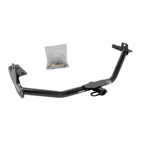
Fastener Kit: 36536F
Wrenches: 17mm, 19mm
Drill Bits: None
Cut Down at Radius
2"
Figure 2
1 1 1 1
Qty. (2)
M12 x 1.75 x 120 Bolt CL8.8
2 2 2 2
Qty. (4)
1/2" Conical Washer
3 3 3 3
Qty. (2)
M12 x 1.75 Nut CL10
1. Lower and remove spare tire from vehicle. The tire release is located underneath the storage compartment in the back of the vehicle.
2. Remove the driver side rear plastic cover, located underneath the vehicle, by using a #2 Phillips head screwdriver to remove fasteners, also remove
(4) plastic push pins. Then remove the passenger side rear plastic cover, located underneath the vehicle, by removing fasteners, and (3) plastic push
pins (Do not discard items).
3. Lower exhaust by removing the rear and side hangers.
4. Raise hitch into position and insert M12 bolts through the bracket and frame as shown in Figure 1. Note: The bumper locator pin may interfere
with the hitch hardware. If necessary, use an angle grinder to trim the locator pin at the shoulder to allow proper hardware clearance.
5. Insert M10 bolts through bracket and into the frame as shown in Figure 1 (Hand tighten).
6. Torque M10 bolts first and then M12 bolts to the specifications below.
7. Reinstall exhaust hangers into mounts.
8. Trim rear plastic covers as shown in Figure 2, then raise into position, reinstall the fasteners and push pins that were removed in Step 2.
CONSULT WITH VEHICLE OWNER BEFORE CUTTING REAR PLASTIC COVERS
9. Reinstall spare tire and make sure it is seated properly.
Tighten all M10 CL10.9 fasteners with torque wrench to 40 Lb.-Ft. (54 N*M)
Note: check hitch frequently, making sure all fasteners and ball are properly tightened. If hitch is removed, plug all holes in trunk pan or other body panels to
prevent entry of water and exhaust fumes. A hitch or ball which has been damaged should be removed and replaced. Observe safety precautions when working
beneath a vehicle and wear eye protection. Do not cut access or attachment holes with a torch.
This product complies with safety specifications and requirements for connecting devices and towing systems of the state of New York, V.E.S.C. Regulation V-5
and SAE J684.
z
2013, 2015 Cequent Performance Products, Inc. – Printed in Mexico
Installation Instructions
Hyundai Santa Fe Sport (5-Passenger)
Fascia
(Sold separately)
Drawbar Kit:
36051
1223
Kia Sorento
Do Not Exceed Lower of Towing Vehicle
Hitch type
Weight Carrying
Ball Mount
Wiring Access Location: SUV1, SUV2
Fasteners typical both sides
45
Figure 1
4 4 4 4
Qty. (4)
M10 x 1.25 x 30 Bolt CL10.9
5 5 5 5
Qty. (4)
7/16" Conical Washer
6 6 6 6
Qty. (1)
Spacer Block, 1/4 x 1 x 2
Tighten all M12 CL8.8 fasteners with torque wrench to 72 Lb.-Ft. (98 N*M)
Sheet 1 of 3
36536N
Part Numbers:
Manufacturer's Rating or
Max Gross
Trailer WT (LB)
3500 Lb (1589 Kg)
6
Spacer Block
10-9-15
36536
90233
06158
Max Tongue
WT (LB)
300 Lb (136 Kg)
Rev. B
Form: F205 Rev C 9-17-2012
Publicidad

Manuales relacionados para Cequent Performance Products 36536


Resumen de contenidos para Cequent Performance Products 36536
- Página 1 This product complies with safety specifications and requirements for connecting devices and towing systems of the state of New York, V.E.S.C. Regulation V-5 and SAE J684. Sheet 1 of 3 36536N 10-9-15 Rev. B 2013, 2015 Cequent Performance Products, Inc. – Printed in Mexico Form: F205 Rev C 9-17-2012...
- Página 2 Ce produit est conforme aux normes V-5 et SAE J684 de la V.E.S.C. (État de New York) concernant les spécifications en matière de sécurité des systèmes d’attelage. z 2013, 2015 Cequent Performance Products, Inc. – Printed in Mexico Feuille 2 de 3...
- Página 3 Este producto cumple con las especificaciones y requisitos de seguridad para conectar dispositivos y sistemas de remolque del estado de Nueva York, V.E.S.C. Regulación V-5 y SAE J684. z 2013, 2015 Cequent Performance Products, Inc. – Printed in Mexico Hoja 3 de 3...