Publicidad
Idiomas disponibles
Idiomas disponibles
Enlaces rápidos
APPARECCHIATURA ELETTRONICA PER CANCELLI A BATTENTE 24Vdc
CONTROL BOARD FOR HINGED GATES 24Vdc
PLATINE ELECTRONIQUE POUR PORTAILS BATTANTS 24Vdc
EQUIPO ELECTRÓNICO PARA PORTONES DE TIPO BATIENTE 24Vdc
ELEKTRONISCHES GERÄT FÜR FLÜGELTORE 24Vdc
JA482C
JA341
ISTRUZIONI PER L'USO – NORME DI INSTALLAZIONE
USE AND INSTALLATION INSTRUCTIONS
INSTRUCTIONS POUR L'EMPLOI – NORMES D'INSTALLATION
INSTRUCCIONES PARA EL USO – NORMAS DE INSTALACIÓN
BETRIEBSANLEITUNG - INSTALLATIONSVORSCHRIFTEN
Publicidad

Manuales relacionados para Genius JA482C


Resumen de contenidos para Genius JA482C
- Página 1 CONTROL BOARD FOR HINGED GATES 24Vdc PLATINE ELECTRONIQUE POUR PORTAILS BATTANTS 24Vdc EQUIPO ELECTRÓNICO PARA PORTONES DE TIPO BATIENTE 24Vdc ELEKTRONISCHES GERÄT FÜR FLÜGELTORE 24Vdc JA482C JA341 ISTRUZIONI PER L’USO – NORME DI INSTALLAZIONE USE AND INSTALLATION INSTRUCTIONS INSTRUCTIONS POUR L’EMPLOI – NORMES D’INSTALLATION INSTRUCCIONES PARA EL USO –...
- Página 2 Una errata installazione o un errato uso del 9) GENIUS is not responsible for failure to observe Good Technique in the prodotto può portare a gravi danni alle persone. construction of the closing elements to be motorised, or for any 2) Leggere attentamente le istruzioni prima di iniziare l’installazione del...
- Página 3 ITALIANO APPARECCHIATURA ELETTRONICA PER CANCELLI A BATTENTE 24 Vdc ISTRUZIONI PER L’USO - NORME DI INSTALLAZIONE 1. CARATTERISTICHE GENERALI Questa centrale di comando per cancelli a battente 24 Vdc, grazie alla elevata potenza del microprocessore di cui è dotata, offre un ampio numero di prestazioni e regolazioni, con rallentamento e controllo motore. Un sofisticato controllo elettronico monitorizza costantemente il circuito di potenza ed interviene bloccando la centrale in caso di anomalie che possano pregiudicare il corretto funzionamento della frizione elettronica.
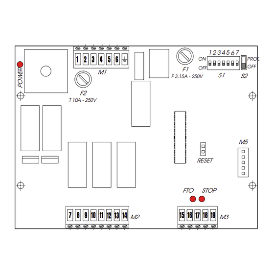
- Página 4 ITALIANO 4. COLLEGAMENTI E FUNZIONAMENTO MORSETTIERA M1 4.1.1 Alimentazione 22V Morsetti “1-2”. Ingresso al quale va collegato il secondario con alimentazione 22 V~ 50/60 Hz del trasformatore. La presen- za di alimentazione per mezzo del trasformatore è segnalata dall’accensione del led POWER. 4.1.2 Batterie Morsetti “3-4”.
- Página 5 ITALIANO 5. INSERIMENTO SCHEDA RICEVITORE PER TELECOMANDO La centrale è predisposta per alloggiare un modulo radioricevitore a 5 pin. Per procedere all’installazione togliere l’ali- mentazione elettrica e inserire il modulo nell’apposito connettore M5 all’interno della centrale. ATTENZIONE: Per non dannegiare, e quindi comprometterne irrimediabilmente il funzionamento, la ricevente deve essere innestata rispettando l’orientamento apecificato nel paragrafo 11 (Schema di collegamento).
- Página 6 ITALIANO l’anta collegata a M2 riparte chiusura, dopo il tempo di sfasamento impostato riparte anche l’anta collegata a M1 fino a raggiungere le battute di chisusura. 10) A questo punto la fase di programmazione è terminata; riporre l’interruttore S2 su OFF, il lampeggiante si spegnerà. 9.
- Página 7 ENGLISH CONTROL BOARD FOR 24 Vdc SLIDING GATES WITH ENCODER OPERATING INSTRUCTIONS – INSTALLATION INSTRUCTIONS 1. GENERAL CHARACTERISTICS Thank to its high powered microprocessor, this control unit for 24 Vdc sliding gates offers a wide range of functions and adjustments, including deceleration and motor control. A sophisticated electronic control monitors the power circuit at all times and disables the control unit in the event of malfunctions that could impair efficiency of the electronic clutch.
- Página 8 ENGLISH 3) If using buffer batteries, secure the relevant support in position B with four Ø3.5x9.5 self-tapping screws (supplied) in the crossover holes of the guides of the sealed enclosure. NB.: the support is sized to house 2 batteries (not supplied) with characteristics and dimensions specified on the table in paragraph 2.
- Página 9 ENGLISH 4.3.4 Photocells Terminals “16-18”. Any safety device (e.g. photocell, sensitive strip, etc.) can be connected to this circuit. By opening a contact, the circuit protects closing motion. The status of this input is signalled by the FTO LED. It also has an effect on opening motion, depending on how dip-switch 4 was set –...
- Página 10 ENGLISH 9. OPERATION OF ELECTRONIC CLUTCH This is a very important device for safety. Its setting does not alter through time, as the device is not subject to wear or setting changes. It is active both at closing and opening. When it operates it reverses motion direction without inhibiting automatic closing if enabled.
- Página 11 FRANÇAIS PLATINE ELECTRONIQUE POUR PORTAILS COULISSANTS 24 Vcc AVEC ENCODEUR INSTRUCTIONS POUR L’EMPLOI – NORMES D’INSTALLATION 1. CARACTERISTIQUES GENERALES Cette centrale de commande pour portails coulissants 24 V cc avec encodeur bénéficie d’un grand nombre de performances et de réglages, avec ralentissement et contrôle moteur, grâce à la puissance élevée du microprocesseur dont elle est équipée. Un contrôle électronique sophistiqué...
- Página 12 FRANÇAIS 5) Fixer la centrale dans la position C avec 4 vis Ø4,2x13 autotaraudeuses (fournies), en plaçant les entretoises entre la platine et les guides du boîtier étanche. Pour la fixation de l’encodeur sur le motoréducteur, procéder comme suit (Fig.2): 1) Fixer sur la calotte A la platine B avec les 4 vis M4x10 C (fournies), en plaçant les entretoises D entre la calotte et la platine.
- Página 13 FRANÇAIS mouvement d’ouverture en fonction de la programmation du dip-switch 4 (voir paragraphe correspondant). Attention ! Si des dispositifs de sécurité ne sont pas connectés, ponter l’entrée. Pour installer plusieurs dispositifs de sécurité connecter les contacts NF en série. 4.3.5 Stop. Bornes “17-18”.
- Página 14 FRANÇAIS 9. FONCTIONNEMENT DE L’EMBRAYAGE ELECTRONIQUE Dispositif très important au plan de la sécurité; son réglage est constant au fil du temps et ne subit aucune usure ou changement de réglage. Il est actif aussi bien pour la fermeture que pour l’ouverture; lorsqu’il intervient, il inverse la marche sans déshabiliter la fermeture automatique si cette dernière est insérée.
- Página 15 ESPAÑOL EQUIPO ELECTRÓNICO PARA VERJAS CORREDERAS 24 Vdc CON ENCODER INSTRUCCIONES DE USO - NORMAS DE INSTALACIÓN 1. CARACTERÍSTICAS GENERALES Esta central de mando para verjas correderas de 24 Vdc con encoder, gracias a la elevada potencia del microprocesador del cual está dotada, ofrece un amplio número de prestaciones y regulaciones, con deceleración y control motor.
- Página 16 ESPAÑOL Para fijar el encoder en el motorreductor, proceda del siguiente modo (Fig.2): 1) Fije sobre la tapa A la tarjeta B con los 4 tornillos M4x10 C (suministrados en dotación), colocando los distanciadores D entre la tapa y la tarjeta. 2) Fije el encoder E con el tornillo M4x30 F (suministrado en dotación) directamente en la rosca que se encuentra en el rotor del motorreductor.
- Página 17 ESPAÑOL Si no se conectan dispositivos de seguridad, puenteen la entrada. Para instalar más dispositivos de seguridad conecten los contactos NC en serie. 4.3.5 Stop Bornes “17-18”. A este circuito debe conectarse cualquier dispositivo (p.ej. pulsador, presostato, etc.) que, al abrir un contacto, detiene el movimiento de la verja.
- Página 18 ESPAÑOL 9. FUNCIONAMIENTO DEL EMBRAGUE ELECTRÓNICO Dispositivo de suma importancia para la seguridad, su tarado es constante en el tiempo sin que esté sujeto a desgaste o cambios de tarado. El embrague electrónico es activo tanto en cierre como en apertura, cuando interviene invierte la marcha sin deshabilitar el cierre automático en caso de que esté...
- Página 19 DEUTSCH ELEKTRONISCHES GERÄT FÜR SCHIEBETORE 24 V DC MIT GEBER BETRIEBSANWEISUNGEN – INSTALLATIONSVORSCHRIFTEN 1. ALLGEMEINE EIGENSCHAFTEN Diese Steuerzentrale für Schiebetore 24 VDC mit Geber bietet aufgrund der hohen Leistungsfähigkeit des Mikroprozessors, mit dem sie ausgestattet ist, umfassende Leistungen und Einstellungen, die die Verzögerung der Bewegung und die Steuerung des Motors einschließen. Eine hochentwickelte elektronische Steuerung überwacht ständig den Hauptstromkreis und blockiert die Steuerzentrale beim Auftreten von Störungen, die den Betrieb der elektronischen Kupplung beeinträchtigen könnten.
- Página 20 DEUTSCH Ø3.5x9.5 (mitgeliefert) an den Überkreuzungsöffnungen der Führungen des abgedichteten Gehäuses befestigen. Anmerkung: Die Größe der Halterung ist so ausgebildet, dass 2 Batterien (Extra) mit den in der Tabelle des Kapitels 2 angegebenen Eigenschaften und Maßen aufgenommen werden können. 4) Die Batterien auf der Halterung positionieren. 5) Die Steuereinheit mit 4 selbstschneidenden Schrauben Ø4.2x13 (mitgeliefert) an der Position C befestigen, wobei die Abstandhalter zwischen Karte und Führungen des...
- Página 21 DEUTSCH 4.3.4 Photozellen Klemmen “16-18”. An diesen Stromkreis werden alle Sicherheitsvorrichtungen (Photozellen, Sicherheitsleiste, usw.) angeschlossen, die beim Ausschalten eines Kontakts eine Sicherheitsfunktion hinsichtlich der Schließbewegung ausüben. Der Status dieses Eingangs wird mit der LED-Diode FTO angezeigt. Je nach der Einstellung des Dip-Schalters 4 wirkt er sich auch auf die Öffnungsbewegung aus, siehe entsprechender Paragraph.
- Página 22 DEUTSCH 9. BETRIEB DER ELEKTRONISCHEN KUPPLUNG Die Einstellung dieser für die Sicherheit der Anlage äußerst wichtigen Vorrichtung bleibt im Verlauf der Zeit unverändert und unterliegt keinerlei Verschleiß oder Einstellungsveränderungen. Die Kupplung ist sowohl bei der Öffnung wie bei der Schließung aktiv, ihr Eingriff führt zu einer Umkehr des Betriebs, ohne dabei die automatische Schließung auszuschalten, soweit diese eingeschaltet ist.
- Página 23 “16”. 24) Sólo puede transitarse entre las hojas si la cancela está completa- 18) GENIUS décline toute responsabilité quant à la sécurité et au bon mente abierta. fonctionnement de l'automatisme si les composants utilisés dans 25) El usuario no debe por ningún motivo intentar reparar o modificar el...
- Página 24 24050 - Grassobbio BERGAMO - ITALIA BERGAMO - ITALIEN The descriptions and illustrations contained in the present manual are not binding. GENIUS reserves the right, whils leaving the main features Declara que: El equipo electrónico JA482C - JA341 erklärt: das elektronisch Gerät JA482C - JA341...