
Manuales relacionados para Briggs & Stratton S1227 Standard Serie


Resumen de contenidos para Briggs & Stratton S1227 Standard Serie
- Página 1 Setup Instructions Instrucciones de montaje Instruction de montage Copyright © Briggs & Stratton Power Products Group, LLC Milwaukee, WI USA All rights reserved. 80014339USCN REV. A...
- Página 2 ADVERTENCIA Safety The safety alert symbol is used to identify safety Si no se leen y siguen las indicaciones information about hazards that can result in personal del manual del operario y todas las injury. A signal word (DANGER, WARNING, or CAUTION) instrucciones de uso, se pueden producir is used with the alert symbol to indicate the likelihood daños materiales, lesiones graves o...
- Página 3 Tools Wrench Sizes 10 / 13 mm Torque Wrench Wire Cutter Air Gauge 10 mm 13 mm Herramientas Llaves de distintos tamaños 10 / 13 mm Llave de torsión Cortador de cables ( lb-ft) Manómetro de aire Outils Tailles des clés 10 / 13 mm Clé...
-
Página 4: Assembly Overview
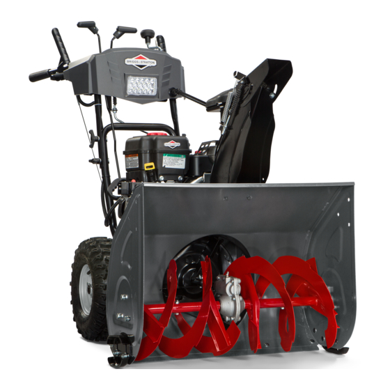
Assembly Overview Auger Shear Pin Replacement Parts are for future service requirements. See Operator’s Manual. Descripción General Del Conjunto Las piezas de repuesto de pasador de seguridad de barrena son para requisitos de mantenimiento a futuro. Consulte el Manual del operador. Aperçu de L’assemblage Les pièces pour le remplacement de la goupille de cisaillement pour tarière sont pour les besoins d’un... -
Página 5: Instalación Del Manillar Inferior
Lower Handle Installation Place lower handle on ground. Line up lower holes on handle and frame, then install hardware, but do not tighten. Lift handle to align upper holes. Install hardware. Tighten all four bolts to torque value shown. Instalación del manillar inferior Coloque el manillar inferior en el suelo. -
Página 6: Instalación Del Manillar Superior
Upper Handle Installation Cut ties on handles. Position upper handle as shown, then install hardware but do not tighten. Install traction drive control cable to inside of handle. Install auger control cable to outside of handle. NOTE: Cable adjusters are set at the factory. No adjustment is necessary. - Página 7 Raise upper handle as shown. Install hardware. Tighten all four wing knobs securely. Check tension on both cables. Cables should deflect slightly with moderate finger pressure. If an adjustment is needed see the Operator’s Manual. Levante el manillar superior como se muestra. Instale las piezas metálicas. Apriete los cuatro pernos de mariposa firmemente.
-
Página 8: Instalación Del Conducto
Chute Installation Insert chute rotation rod through dash panel into mating gear. Install chute with hardware as shown but do not tighten. Rotate the chute crank to ensure rod is rotating freely. Tighten both nuts to torque value shown. Instalación del conducto Inserte la varilla de giro del conducto a través del panel con guiones hacia el engranaje correspondiente. -
Página 9: Instalación Del Cable Del Deflector
Deflector Cable Installation Move deflector control lever all the way forward. Route deflector cable around handle as shown. Fit cable through wire hanger on engine. Push deflector down while fitting cable end into hole on deflector bracket. Fasten cable into bracket on chute and tighten one of the nuts securely. Rotate the chute crank counterclockwise until it stops. Fasten cable to lower handle with tie down strap. -
Página 10: Instalación De La Varilla De Control De Velocidad
Speed Control Rod Installation Move speed control lever all the way forward. Attach upper control rod to bracket as shown. Attach lower control rod with spring to the speed control arm. Fasten hardware as shown. NOTE: Rod adjuster is set at the factory. No adjustment is necessary. - Página 11 Fasten Harness Connection Fasten headlight harness connections. Fasten harness to lower handle with tie wire. Fijación de la conexión del haz de cables Fije las conexiones del haz de cables de la luz delanteras. Fije el haz de cables en el manillar inferior con la amarra. Attacher la connexion du faisceau Attacher les connexions du faisceau de phare.
-
Página 12: Instalación De La Zapata
Skid Shoe Installation Install skid shoes with hardware as shown. Determine the clearance then, adjust the skid shoes so the scraper bar has a certain amount of clearance above a hard surface (A) or a gravel-covered / uneven surface (B). Place a block (C) with the thickness equal to the desired ground clearance under the scraper bar. -
Página 13: Revise Y Ajuste La Presión De Los Neumáticos
Check and Adjust the Tire Pressure The maximum pressure is stamped on the sidewall of the tires. Do not exceed this pressure. WARNING Over-inflating tires may cause them to explode which could result in serious injury. DO NOT inflate the tires above the maximum pressure.. Revise y Ajuste la Presión de los Neumáticos La presión máxima está impresa en la pared lateral de los neumáticos. No exceda esta presión. ADVERTENCIA Inflar en exceso los neumáticos puede causar que exploten, lo que puede provocar lesiones graves. -
Página 14: Check Oil Level
Check Oil Level See operator’s manual for oil specifications. Place snowthrower on a level surface. Remove dipstick. Keep oil level in the operating range. Verificación del nivel de aceite Consulte el Manual del operador para conocer las especificaciones de aceite. Coloque el lanzanieve en una superficie nivelada. Retire la varilla de aceite. Mantenga el nivel del aceite en el rango de operación. Vérifier le niveau d’huile Voir le manuel de l’opérateur pour les spécifications concernant l’huile. -
Página 15: Prueba Del Sistema De Seguridad
Safety System Test Prueba del Sistema de Seguridad PELIGRO Peligro de amputación DANGER Amputation hazard Este lanzanieve contiene una barrena giratoria que This snowthrower contains a rotating augar to throw lanza la nieve. Los dedos o los pies se pueden snow. - Página 16 Test du système de sécurité DANGER Risque d’ amputation Cette souffleuse à neige contient une tarière rotative pour éjecter la neige. Les doigts et les pieds se coincer facilement dans la tarière entraînant une amputation drastique ou une grave lacération. Si l’unité...