Tabla de contenido
Publicidad
Idiomas disponibles
Idiomas disponibles
Enlaces rápidos
Publicidad
Capítulos
Tabla de contenido

Resumen de contenidos para Albatross Alba-Engine NMEA2000
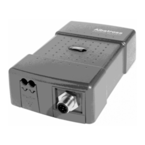
- Página 1 USER MANUAL MANUAL DE USUARIO Alba-Engine Analog to NMEA2000 engine data interface Conversor de datos de motor analógicos a NMEA2000 © COPYRIGHT 2009 EMMI Network S.L. All rights reserved - 30728283 Rev PA6 27-01-2009...
- Página 2 English version ……………………………………………... 3 Versión en español …………………………………………40...
- Página 3 Document revisions Revision Date Comments/Changes 2006-11-28 First version 2006-12-22 Minor updates 2007-01-02 Connection diagram to VDO gauges updated 2007-01-22 Format review 2008-07-01 Config Tool configuration (Revision 1.6) 2009-01-27 Format revision No part of this document may be reproduced in any form without the written permission of the copyright owner.
-
Página 4: Tabla De Contenido
Contents Introduction...........................5 Specifications ..........................6 Quick installation ..........................7 3.1. Unpacking the unit ........................7 3.2 Choosing a location to mount the module ..................8 3.2.1. Module location if analogue gauges are already present ...........8 3.2.2. Module location when the vessel contains analogue gauges………………………………10 3.3 Alba-Engine Connections......................12 3.3. -
Página 5: Introduction
The purpose of this document is to provide the user with the necessary instructions for the installation and usage of the NMEA 2000 Albatross Alba-Engine interface. The NMEA 2000 Albatross Alba- Engine is a device intended to monitor NME A2000 marine motors. -
Página 6: Specifications
2. Specifications The Albatross Alba-Engine interface has the following specifications: • NMEA 2000 interface • Adapts standard (10-180 ohm) European resistive sensors to the NMEA 2000 network. • Adapts standard (30-240 ohm) American resistive sensors to the NMEA 2000 network. -
Página 7: Quick Installation
4 Interface configuration. 5 Sensor calibration depending on its commercial model. 6 Optional: Custom sensor calibration 3.1. Unpacking the unit When you unpack the box containing your Albatross Alba-Engine interface, you should find the following elements: Alba-Engine interface Alba-Engine User Manual... -
Página 8: Choosing A Location To Mount The Module
3.2. Choosing a location to mount the module Figure 1. Module mounting 3.2.1. Module location if analogue gauges are already present Alba-Engine has two types of connection: 1 – Motor sensors connection 2 – NMEA 2000 network connection... - Página 9 Thus, the Alba-Engine interface should be placed between the main NMEA 2000 network and the analogue gauges. This is because you'll have to connect some wires from the interface to the back of the gauges and others to the NMEA network.
-
Página 10: Module Location When The Vessel Contains Analogue Gauges
3.2.2. Module location when the vessel contains analogue gauges Alba-Engine has two kinds of connections: 1 – To the motor sensors 2 – To the NMEA 2000 network Thus, it should be connected between the main NMEA-2000 network and the analogue gauges. This is because you’ll have to connect some cables to the back of these gauges, and the interface to the NMEA network. - Página 11 Figure 3. Connection diagram of the module in parallel with analogue gauges...
-
Página 12: Alba-Engine Connections
2 – NMEA 2000 network connection You should also take into account that Alba-Engine requires an Alba-USB connected to a laptop computer to configure the sensors once all the connections are ready PC with Albatross ConfigTool Alba-Engine module Alba-USB Figure 4 Wiring diagram to the Alba-USB... -
Página 13: Alba-Engine Connection To A Motor With Vdo Analogue Gauges
3.3.1 Alba-Engine connection to a motor with VDO analogue gauges Alba-Engine can work together with analogue motor gauges without affecting their measuring. To make this kind of connection you will have to follow the instructions given in the following illustrations 1.- Signal 3.3.1 .1 Connection to a Tachometer For this type of connection you'll need to derive... - Página 14 3.3.1 .2 Connection to a pressure or temperature gauge You'll need to unscrew the connector’s nut in these gauges and hook a new cable to be connected to either the 4, 6, 8 or 10 inputs in the Alba-Engine. Proposed cable Gauge terminals colour Tensión (+, +12V, I, IGN)
-
Página 15: Alternator And Mass Connection
3.3.2 Alternator and mass connection To connect the alternator’s input and measure the incoming voltage from it, you’ll need to connect a cable to the +V connector in the voltmeter gauge. If your motor’s control panel has no voltmeter, locate the alternator’s connection to the battery bank. -
Página 16: Alba-Engine Connection To A Motor With No Control Panel
3.3.3 Alba-Engine connection to a motor with no control panel If you have a motor with no control panel, you’ll need to connect Alba-Engine’s inputs directly to the motor sensors following this diagram: NEGATIVE W SIGNAL/ SENSOR NEGATIVE RESISTIVE SENSOR NEGATIVE RESISTIVE SENSOR NEGATIVE... -
Página 17: Conexión Al Bus Nmea2000
3.3. 4 Connection to NMEA 2000 bus The Alba-Engine interface can connect to a NMEA 2000 bus through a 5- pin Micro- C connector. You’ll have to connect the Alba-Engine interface to the NMEA 2000 bus using a cable of the suitable length from the module to a T-connector to the main network. - Página 18 3.3.4.5 Albatross system integration Figure 15A. Connection diagram of the Alba-Engine to a laptop with Alba-USB and Albatross ConfigTool...
- Página 19 Figura 15B. Connection diagram of the Alba-Engine to an Albatross System...
-
Página 20: Alba-Engine Configuration
3.4 Alba-Engine Configuration The following illustration shows the main configuration screen for the Alba-Engine interface. Figure 16. Main dialog box for the configuration of the Alba-Engine To ensure the proper functioning of your vessel, you need to configure each and every parameter in this dialog before using it. -
Página 21: Nmea Instance Number And Address
3.4.1 NMEA instance number and address Most manufacturers use an instance number to reference the motor the interface inserts data about in the NMEA bus. We recommend you to use the following table to assign the correct instance number. Nuber of engines Engine Instante number Babor... - Página 22 3.4.1.1 Impulses per turn for RPM Impulses per turn tell the Alba-Engine how many signals the alternator receives before the motor completes a revolution per minute. 100 impulses per turn is the norm, but this value may vary slightly, depending on the manufacturer of the alternator. Figure 18.
- Página 23 3.4.1.3 Choice of parameters to be measured On inputs 2, 3, 4 and 5 the user can choose what parameters to represent on the digital display. The available parameters are: Boost pressure Oil pressure Coolant water pressure Oil temperature Coolant water temperature Figure 21.
- Página 24 3.4.1.4 Choice of sensor type As seen in section 2, motor sensors are either resistive or voltage-based (VDO). You must choose the appropriate type of sensor connected for each parameter to be measured. Once you have changed all the necessary fields in the dialog box, click “Accept” for all information to be programmed and stored in the Alba-Engine interface’s memory.
-
Página 25: Sensor Calibration And Commercial Brand Choice
3.4.2 Sensor calibration and commercial brand choice Once sensor and measure units have been chosen, it’s time to click on the “Calibrate” button for inputs 2 to 5. On pushing it, a new window will open where you can choose the sensor gauge’s brand and model to follow. -
Página 26: Custom Sensor Calibration
3.4.2.2 Voltage correction enabled? If you connected the Alba-Engine in parallel with VDO gauges, you’ll have to note the tension at which the configuration is being set in this field (see the initial screen of Installtool, Figure 4) and check the toggle box marked “enabled”. You’ll also have to enter the voltage value at which the measurement was made (in figure 23, the example is 12,29 V) Reference voltage By checking this field, you’ll tell Alba-Engine that the voltage your ship works on may change during... -
Página 27: Technical Specifications
3.7 Technical specifications SPECIFICATIONS MECHANICAL SPECIFICATIONS Magnetic sensor / W signal Size & Weight 143mm x 86mm x 38mm , 230g. Input 4 x Resistive sensor (0 to 250 Ohm) Weight 230g DC tension:. 32V DC max. Mounting Surface, screwed on RPM: ±100rpm Case material Polycarbonate UL94V0... -
Página 28: Technical Support
3.8 Technical support Emmi Network provides the user with complete technical support through its webpage and a customer support hotline. Please use any of these means to contact us if a problem arises that you can’t solve. Please visit the customer support area in our webpage: http://www.albatrosscontrol.com/en/tech/ Customer support hotline If you happen not to have Internet access, please call the following phone number:... - Página 30 Revisiones del documento Revisión Fecha Comentarios/Cambios 2006-11-28 Primera versión 2006-12-22 Actualizaciones menores 2007-01-02 Actualización esquemas conexionado relojes VDO 2007-01-22 Revisión de formato 2008-07-01 Configuración con Config Tool (Versión 1.6) 2009-01-27 Revisión de formato Ninguna parte de este documento puede ser reproducida sin la aprobación explicita del propietario del copyright.
- Página 31 Tabla de Contenidos Introducción ........................32 Caracteristicas ......................33 Instalación........................34 3.1. Desembalaje......................34 3.2. Montaje del módulo ....................35 3.2.1. Localización cuando no existan relojes analógicos en el barco......35 3.3. Conexiones del Alba-Engine..................39 3.3.1 Conexiones del Alba-Engine a un motor con relojes VDO ........40 3.3.2 Conexiones al alternador y masa .................42 3.3.3 Conexiones del Alba-Engine a un motor sin panel de control ......43 3.3.
-
Página 32: Introducción
1. Introducción Gracias por adquirir su nuevo componente del sistema de control digital Albatross. Este manual contiene información importante relativa a la instalación, operación y mantenimiento de su nuevo sistema de control digital. Para obtener el mayor rendimiento del mismo le rogamos que lea completamente este manual. -
Página 33: Caracteristicas
2. Caracteristicas El interface Albatros Alba-Engine posee las siguientes características: • Interface NMEA 2000 • Adapta sensores resistivos estándar europeos de (10-180ohm) a la red NMEA 2000 • Adapta sensores resistivos estándar americanos (30-240 ohm) a la red NMEA 2000 •... -
Página 34: Instalación
3. Instalación Para instalar el interface Alba-Engine deberá completar los siguientes pasos. Por favor, estudie cada uno de las secciones individuales referenciadas para obtener una información más detallada de cada uno de ellos: Desembalar la caja. Seleccionar una localización para el montaje del interface. Conectar el interface. -
Página 35: Montaje Del Módulo
3.2. Montaje del módulo Figura 1. Montaje del módulo. 3.2.1. Localización cuando no existan relojes analógicos en el barco El Alba-Engine tiene dos tipos de conexiones: Conexiones con los sensores del motor Conexión con la red NMEA 2000... - Página 36 El lugar de colocación del interface no es crítico y teniendo en cuenta las distancias anteriores y que los cables y conectores NMEA son aprueba de agua, (IP 67 protección contra inmersiones temporales en agua) el interface podría colocarse virtualmente en cualquier lugar de la embarcación.
-
Página 37: Localización Cuando Existan Relojes Analógicos En El Barco
3.2.2. Localización cuando existan relojes analógicos en el barco El Alba-Engine tiene dos tipos de conexiones: 1 – Conexiones con los sensores del motor 2 – Conexión con la red NMEA 2000 Por tanto, el Alba-Engine debe colocarse entre la red troncal NMEA 2000 y los relojes analógicos. La razón es que deberá... - Página 38 Figura 3. Esquema de conexión del módulo a relojes analógicos...
-
Página 39: Conexiones Del Alba-Engine
También deberá tener en cuenta que el Alba-Engine necesita de un Alba-USB conectado a un ordenador portátil para poder configurar los sensores una vez estén realizadas todas las conexiones) Módulo Alba-Engine PC con Albatross ConfigTool Alba-USB Figura 4. Esquema de conexión del módulo a relojes analógicos... -
Página 40: Conexiones Del Alba-Engine A Un Motor Con Relojes Vdo
1.- Señal 3.3.1 Conexiones del Alba-Engine a un motor con relojes VDO El Alba-Engine puede funcionar conjuntamente con los relojes analógicos del motor sin afectar a sus mediciones. Para realizar este tipo de conexionado deberá seguir las instrucciones de la siguientes ilustraciones 3.3.1 .1 Conexión a tacómetro En esta conexión deberá... -
Página 41: Conexión A Un Reloj De Presión O Temperatura
3.3.1 .2 Conexión a un reloj de presión o temperatura En estos relojes, deberá desenroscar la tuerca del conector y enganchar un nuevo cable que deberá conectar a las entradas 4, 6, 8 o 10 del Alba-Engine. Color del cable Terminales del reloj propuesto Tensión (+, +12V, I, IGN) -
Página 42: Conexiones Al Alternador Y Masa
3.3.2 Conexiones al alternador y masa En estos relojes, deberá desenroscar la tuerca del conector y enganchar un nuevo cable que deberá conectar a las entradas 4 Para conectar la entrada del alternador y poder medir el voltaje que proporciona el mismo, deberá... -
Página 43: Conexiones Del Alba-Engine A Un Motor Sin Panel De Control
3.3.3 Conexiones del Alba-Engine a un motor sin panel de control En los motores que no dispongan de panel de control deberá conectar las entradas del Alba- Engine, directamente a los sensores del motor según el siguiente esquema: NEGATIVO SEÑAL W/CAPTADOR NEGATIVO SENSOR RESISTIVO NEGATIVO... -
Página 44: Conexión Al Bus Nmea2000
3.3. 4 Conexión al bus NMEA2000 EL interface Alba-Engine proporciona una conexión al bus NMEA 2000 a través de un conector Micro- C de 5 patillas. Usted deberá conectar el interface Alba-Engine al bus NMEA utilizando un cable con la longitud apropiada que vaya desde el módulo a una “T” de conexión con la red troncal. Asegúrese de que el cable se ha quedado firmemente conectado y con el collar del conector firmemente roscado. -
Página 45: Integración Con Sistema Albatros
3.3.4.5 Integración con sistema Albatros Figura 15A. Esquema de conexión del Alba-Engine para configuración del módulo... - Página 46 Figura 15B. Esquema de conexión del Alba-Engine para integración en Albatross On Board...
-
Página 47: Configuración Del Alba-Engine
3.4 Configuración del Alba-ENGINE En la siguiente ilustración puede observarse la pantalla de configuración principal del interface Alba-Engine. Figura 16. Cuadro de diálogo principal de configuración del Alba-Engine Para asegurar un correcto funcionamiento en su barco, es necesario configurar cada uno de los parámetros que aparecen en el mismo antes de su uso. -
Página 48: Número De Instancia Y Dirección Nmea2000
3.4.1 Número de instancia y dirección NMEA2000 La mayoría de fabricantes utilizan el número de instancia para referenciar el motor al que corresponden los datos que el interface inserta en el bus NMEA. Le recomendamos que utilice la siguiente tabla para asignar el número de instancia correcto: Número de motores Motor Número de instancia... -
Página 49: Impulsos Por Vuelta Para Las Rpm
3.4.1.1 Impulsos por vuelta para las RPM Los impulsos por vuelta le indican al Alba-Engine cuantas señales le llegan del alternador antes de que el motor haya dado una revolución por minuto. Lo usual son 100 impulsos por vuelta pero es posible que varíe ligeramente según el fabricante del alternador. -
Página 50: Selección De Los Parámetros A Medir
3.4.1.3 Selección de los parámetros a medir En las entradas 2, 3, 4 y 5 podemos elegir los parámetros que vamos a representar en nuestra pantalla digital. Estos parámetros pueden ser: Presión de turbo Presión de aceite Presión de agua de refrigeración Temperatura de aceite Temperatura de agua de refrigeración Figura 20. -
Página 51: Selección Del Tipo De Sensores
3.4.1.4 Selección del tipo de Sensores Como se ha visto en la sección 2, los sensores del motor pueden ser resistivos o por voltaje (VDO). Seleccione para cada uno de los parámetros a medir el tipo de sensor conectado. Una vez haya cambiado todos los campos del cuadro de diálogo. Pulse el botón “Aceptar” para que la información se programe y almacene en la memoria del interface Alba-Engine. -
Página 52: Calibración Del Sensor Y Selección De La Marca Comercial
3.4.2 Calibración del sensor y selección de la marca comercial Una vez ha seleccionado qué sensor y qué medida está realizando, es el momento de pulsar el botón “Calibrar” para cada una de las entradas de la 2 a la 5. Al pulsar este botón se abrirá... -
Página 53: Calibración De Sensores Personalizada
3.4.2.2 Corrección de voltaje ¿habilitado? Si usted ha conectado el Alba-Engine en paralelo con relojes VDO, deberá apuntar en este campo la tensión a la que está realizando la configuración (ver en pantalla inicial de ConfigTool, figura 4) y marcar la casilla de verificación “habilitado”. Por otra parte, deberá introducir el valor del voltaje en el que ha realizado la medición. -
Página 54: Especificaciones Técnicas
3.7 Especificaciones técnicas MECÁNICAS ESPECIFICACIONES Sensor magnético / Señal W Dimensiones 143mm x 86mm x 38mm Entrada 4 x Sensor resistivo (0 a 250 Ohm) Peso 230g Tensión DC: máx. 32V DC Superficie, fijación por RPM: ±100rpm Montaje tornillos Precisión Sensor resistivo: 1% Tensión DC: 1% Material caja... -
Página 55: Soporte Técnico
3.8 Soporte técnico Emmi Network proporciona un completo soporte técnico en la Web y a través de la línea telefónica de soporte. Por favor, use cualquiera de estos métodos si no puede resolver un problema. Por favor, visite el área de soporte técnico en: http://www.albatrosscontrol.com/es/tech/ E-mail Puede ponerse en contacto con el soporte técnico en la dirección: support@emminet.com...