Tabla de contenido
Publicidad
Enlaces rápidos
Franklin electric Co., Inc.
Oklahoma City, OK
www.LittleGiantPump.com
customerservice@lgpc.com
EN
This instruction sheet provides you with the information required to safely own
and operate your product. Retain these instructions for future reference.
The product you have purchased is of the highest quality workmanship and
material, and has been engineered to give you long and reliable service. This
product has been carefully tested, inspected, and packaged to ensure safe
delivery and operation. Please examine your item(s) carefully to ensure that no
damage occurred during shipment. If damage has occurred, please contact the
place of purchase. They will assist you in replacement or repair, if required.
ReAd THeSe INSTRUCTIoNS CAReFUllY BeFoRe ATTeMPTING To
INSTAll, oPeRATe, oR SeRVICe YoUR PRodUCT. KNoW THe PRodUCT'S
APPlICATIoN, lIMITATIoNS, ANd PoTeNTIAl HAZARdS. PRoTeCT
YoURSelF ANd oTHeRS BY oBSeRVING All SAFeTY INFoRMATIoN.
FAIlURe To CoMPlY WITH THeSe INSTRUCTIoNS CoUld ReSUlT IN
PeRSoNAl INJURY ANd/oR PRoPeRTY dAMAGe!
deClARATIoN oF CoNFoRMITY
We, Franklin Electric, declare that our pumps TPR, TPT & TPS with pump type
and serial number as shown on the nameplate are constructed in accordance
with Directives 2006/95/EC and 89/336/EEC and assume full responsibility for
conformity with the standards laid down therein.
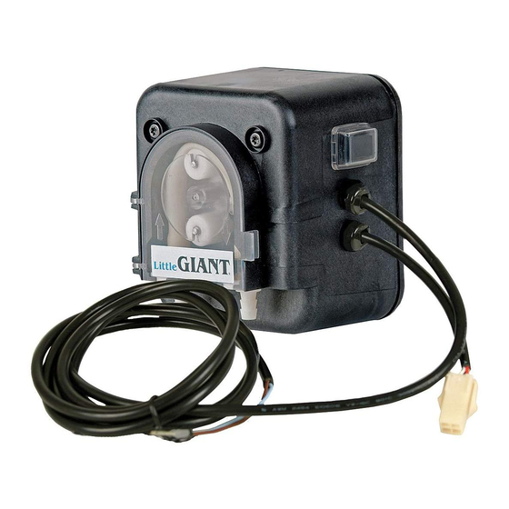
deSCRIPTIoN
Your Little Giant peristaltic condensate pump is designed as a fully automatic
condensate removal system for the water dripping off an air conditioner
evaporator coil. The pump is not for contiuous use applications. The pump you
have purchased is a small but powerful drain pump for the positive displacement
of condensate from fan coils and air conditioners. The design of this pump allows
the air handler to be located away from gravity water drains since the condensate
can be pumped to a common drain a distance away. The peristaltic pump is
designed to remove condensation from fan coil, wall-mount, ceiling and cassette
air conditioning equipment.
SAFeTY GUIdelINeS
SHUT oFF eleCTRICAl PoWeR AT FUSe BoX BeFoRe ATTeMPTING To
SeRVICe, dISCoNNeCT, CoNNeCT oR ReMoVe ANY CoMPoNeNT!
1. This pump is not to be used to pump flammable or explosive fluids such
as gasoline, fuel oil, kerosene, etc. Do not use this pump in explosive
atmospheres.
2. Do not handle pump with wet hands or when standing on a wet, damp
surface or when standing in water.
3. In any installation where property damage and/or personal injury might result
from an inoperative or leaking pump due to power outages, discharge line
blockage, or any other reason, a backup system(s) and/or alarm should be
used.
4. Support pump and piping when assembling and when installed. Failure to
do so may cause piping to break, pump to fail, motor bearing failures, etc; or
may cause the pump to malfunction.
5. Place pump in an area where there is no danger of ingress of water.
SPeCIFICATIoNS
Maximum suction head:
Maximum delivery head:
Maximum ambient temperature: 50°C (122°)
PRe-INSTAllATIoN
1. Check the pump label for proper voltage and frequency required. Do not
connect to voltage and frequency other than that shown.
2. It is recommended to use ¼" I.D. or 6 mm I.D. tubing for both the inlet and
outlet. Inlet tubing is connected to the inlet fitting identified by an upward
arrow. Outlet or discharge tubing is connected to the outlet fitting identified
by a downward arrow.
3. Make sure the transparent cover is closed before operating.
INSTAllATIoN
Pump Mounting Installation:
The pump can be mounted adjacent, below or above (but not more than 2m
above) the condensate water source.
For best results, mount the pump with the hose connections facing down as
shown in Figure 1B.
ModelS • ModèleS •
Modelos
TPS • TPT • TPR
ENGLISH
2m (6.5 ft)
14m (49 ft)
A
B
The pump may also be positioned on any side, but not placed rotor downward
(Figure 1C) or upward (Figure 1A). Connect 6.0mm or 1/4" tubing (not provided)
to the pump intake indicated by the arrow pointing upward on the transparent
cover. Position the other end of the intake tube in the drip tray drain hose and
seal it accordingly or place the intake tube in the drip tray (Figure 2). Be careful
not to twist, kink, or collapse the tubing. Run a length of 6.0mm or ¼" tubing (not
provided) from the discharge of the pump to a gravity drain. Refer to Figure 2 for
maximum vertical and horizontal discharge capabilities.
16 ft (5 m)
max
"Your Solution Innovator"
Red end: room air
6.5 ft (2 m) max
sensor, intake air
Coil
Blue end: cold air
sensor, intake air
Block off unit drain
Internal drain tray
Wall or below ceiling A/C unit
CAUTIoN: Be certain that there are no sharp bends or kinks in the suction and
discharge tubing. Keep all tubing and cables clear of moving parts in the air
handler. If using Ty-raps to secure tubing, be certain the Ty-rap does not collapse
tubing.
Collection Reservoir Installation (R Series only):
Locate the float reservoir in a suitable position below the bottom level of the drip
tray of the air conditioner. Be certain that the reservoir is within (+/-) 15 degrees
of being level. Optimum performance is achieved when the reservoir is level. If the
reservoir is not mounted properly, the float mechanism may not function properly
and may overflow.
Attach the 13mm (1/2") tube (provided) to the reservoir intake and the drip tray
outlet or drain hose. Be certain to support the reservoir when attaching tubing
and make sure the tubing is not twisted, kinked or collapsed when reservoir is
in place. Connect the long 4 x 6 mm (5/32") tubing (provided)to the discharge
of the reservoir marked "PUMP". Connect the other end of the 4 x 6 mm (5/32")
tubing to the provided 4 x 6 mm adapter. Use a short piece of 6 mm or ¼" tubing
(not provided) to connect the 4 x 6 mm adapter to the pump inlet fitting identified
by an upward arrow. Connect the short 4 x 6 mm (5/32") tubing (provided) to
the outlet of the reservoir marked "VENT". The free end of the tubing must be
directed upward above the drip tray to prevent overflow. Be certain the tubing is
not twisted, kinked or collapsed when installed.
eleCTRICAl CoNNeCTIoNS
SHUT OFF ELECTRICAL POWER AT FUSE BOX BEFORE MAKING ANY
CONNECTIONS. ALL WIRING MUST COMPLY WITH LOCAL CODES. CHECK
THE PUMP LABEL FOR PROPER VOLTAGE REQUIRED. DO NOT CONNECT TO
VOLTAGE OTHER THAN THAT SHOWN.
TPS Series (compressor or cooling signal) - Connect the brown wire to the main
phase (line), the blue wire to the neutral phase (common). The pump must not
be connected to a switched line. Electricity should always be provided on this
line. Connect the orange wire to the compressor or cooling signal (Figure 3).
When the compressor engages, a 230V supply voltage will be sent to start the
pump. When the compressor stops operating, the pump will not stop. The pump
is programmed to continue operating for another 5 minutes to collect any residual
condensate before stopping.
NoTe: The compressor or cooling signal neutral phase (common) needs to be
the same neutral phase (common) that is used to supply power to the controller.
TPT Series (temperature signal) FOR PROPER PUMP OPERATION, PLEASE
FOLLOW THESE INSTRUCTIONS: Connect the brown wire to the main phase
(line) and the blue wire to the neutral phase (common) (Figure 2). Make sure
power is off when connecting the temperature sensor to the pump. Connect the
sensor cable to the pump by connecting the 4-prong plug to the corresponding
C
FIGURe 1
TPT
98 ft (30 m)
max
Lt. blue
Brown
To pump
Ceiling
Internal
drain tray
Alternative position for inlet tube
FIGURe 2
D
46 ft (14 m)
max
Inlet tube fixed
inside tray
outlet with
sealant
1
Publicidad
Tabla de contenido

Manuales relacionados para Franklin Electric Little GIANTS TPS


Resumen de contenidos para Franklin Electric Little GIANTS TPS
- Página 1 Brown "Your Solution Innovator" deClARATIoN oF CoNFoRMITY We, Franklin Electric, declare that our pumps TPR, TPT & TPS with pump type and serial number as shown on the nameplate are constructed in accordance To pump with Directives 2006/95/EC and 89/336/EEC and assume full responsibility for Red end: room air 6.5 ft (2 m) max...
-
Página 2: Declaration De Conformite
After electrical connections have been made, check the pump for proper deClARATIoN de CoNFoRMITe operation. Press the test switch to determine if pump operates properly. Nous, Franklin Electric déclarons que les pompes TPR, TPT, TPS modèle et numero de série marqués sur la plaque signalétique sont conformes aux SeRVICe INSTRUCTIoNS Directives 2006/95/EC, 89/336/EEC. -
Página 3: Avertissement Directives De Sécurité
WARNING AVERTISSEMENT dIReCTIVeS de SÉCURITÉ AVERTISSEMENT COUPER L’ALIMENTATION ÉLECTRIQUE À PARTIR DE LA BOÎTE À FUSIBLES AVANT D’EFFECTUER L’ENTRETIEN, DE DÉBRANCHER, DE BRANCHER OU D’ENLEVER UNE COMPOSANTE! 1. Ne pas utiliser la pompe pour pomper des liquides inflammables ou explosifs comme de l’essence, du mazout, du kérosène, etc. -
Página 4: Declaracion De Conformidad
CoNFoRMIdAd AVERTISSEMENT En Franklin Electric declaramos bajo nuestra exclusiva responsabilidad que las bombas TPR, TPT, y TPS modelo y numero de serie marcados en la placa de Lorsque les connexions électriques sont complétées, vérifier le bon caracteristicas son conformes a las disposiciones de las Directivas 2006/95/EC, fonctionnement de la pompe. -
Página 5: Instalacion
2. Se recomienda el uso de tubería con D.I. de 6mm o un ¼ de pulg. tanto en CoNeXIoNeS eleCTRICAS! la entrada como en la salida. La tubería de entrada se conecta al accesorio ADVERTENCIA de entrada identificado con una flecha hacia arriba. La tubería de salida o descarga se conecta al accesorio de salida identificado con una flecha hacia APAGUE LA ENERGÍA ELÉCTRICA EN LA CAJA DE FUSIBLES ANTES DE abajo. -
Página 6: Mantenimiento
La capacidad del circuito de alarma es de 200 VCC, 1 amperio máximo y 15 vatios máximo. Bomba a suministro de energía: Marrón - fase principal (línea) Azul - fase neutra (común) Después de realizar las conexiones eléctricas, cerciórese de que la bomba funcione debidamente. -
Página 7: Garantie Limitée
RECOURS EXCLUSIF DE L’ACHETEUR POUR UN PRODUIT DÉFECTUEUX. absence of suitable proof of purchase date, the warranty period of this product will begin Franklin Electric Company, Inc et ses filiales (ci-après « la Société ») garantit que les to run on the product’s date of manufacture. -
Página 8: Garantia Limitada
RECURSO QUE TENDRÁ EL COMPRADOR ANTE UN PRODUCTO DEFECTUOSO. LA CORRECCIÓN DE DISCONFORMIDAD, DE LA MANERA Y EN EL PERÍODO DE Franklin Electric Company, Inc y sus subsidiarias (en adelante “la Compañía”) TIEMPO ESTABLECIDOS ANTERIORMENTE, CONSTITUIRÁ EL CUMPLIMIENTO DE garantizan que los productos que están acompañados por esta garantía se TODA LA RESPONSABILIDAD DE LA COMPAÑÍA CON EL COMPRADOR YA SEA...