Tabla de contenido
Publicidad
Idiomas disponibles
Idiomas disponibles
Enlaces rápidos
Publicidad
Tabla de contenido

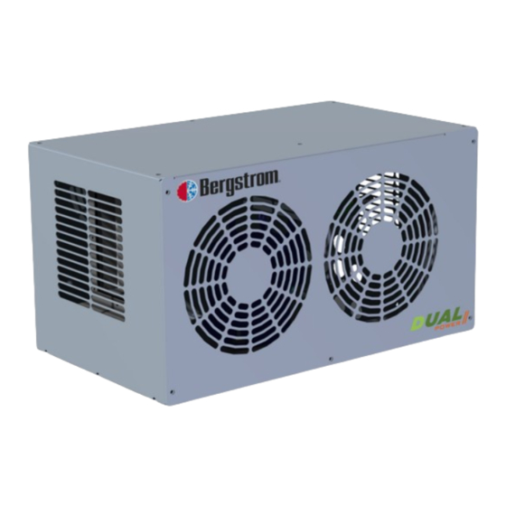
Resumen de contenidos para Bergstrom DUAL POWER II
- Página 1 Instrucciones de Montaje Spanish Mounting Instructions English Instructions de Montage French Montageanweisungen German Calidad en Empresa Automoción Registrada 1002447392 IATF 16949 ISO 9001...
-
Página 2: Recomendaciones Para El Montaje
Aire Acondicionado de vehículos. • Apretar siempre los racores usando 2 llaves para evitar roturas. Bergstrom queda exenta de responsabilidad si se producen averías que procedan de una inadecuada manipulación o instalación del equipo, Par de apriete (N.m) -
Página 3: Compresor - Condensador
DUAL POWER II COMPRESOR - CONDENSADOR 1- Posicionar unidad compresor - condensador en el sitio más adecuado dependiendo del vehículo. 2- Si es necesario se deberán fabricar soportes resistentes para su colocación. 3- Montar conjunto con tornillos 8/125x25. - Página 4 DUAL POWER II TABLA DE REFERENCIA PARA CANTIDAD DE ACEITE A INTRODUCIR Y CARGA DE GAS Longitud total C.C. Aceite Carga de gas de tuberías a introducir a introducir 20 c.c. 450 grs. 35 c.c. 50 c.c. 65 c.c. 500 grs.
-
Página 5: Esquema Eléctrico
DUAL POWER II ESQUEMA ELÉCTRICO Relé Relé 7,5A (24V) Fusible 10A (12V) Centro de alimentación 10A (24V) Fusible 15A (12V) Resistencia Sensor de temperatura Módulo electrónico Compresor Presostato Electros Azul Negro Rojo Verde Blanco Amarillo Na Naranja Marrón... - Página 6 The installing personnel must have a sufficient training in vehicles air conditioning. Bergstrom shall not be responsible for breakdowns or damages coming from an inadequate handling or Tightening torque (N∙m) installation of the equipment or from modifications...
- Página 7 DUAL POWER II COMPRESSOR - CONDENSER 1- Position the condenser-compressor unit in the most suitable place, depending on the vehicle. 2- If necessary, manufacture resistant supports for positioning. 3- Mount the unit with 8/125x25 screws.
- Página 8 DUAL POWER II TABLE OF REFERENCE FOR ENTRIES AMOUNT OF OIL AND GAS CHARGING C.C. Oil to be Gas load to be Total pipe length introduced introduced 20 c.c. 450 grs. 35 c.c. 50 c.c. 65 c.c. 500 grs. 10 m 80 c.c.
-
Página 9: Wiring Diagram
DUAL POWER II WIRING DIAGRAM Relay Relay Power source Fuse 10A (24V) 15A (12V) Resistance Temperature sensor Compressor module Compressor Pressure switch Fans Blue Black Green White Yellow Na Orange Brown... -
Página 10: Avertissements
• Serrer toujours les raccords avec 2 clés pour éviter les cassures. L’installateur devra posséder la formation pertinente en air conditionné sur véhicules. Bergstrom ne sera pas responsable des dommages Couple de serrage (N.m) ou des bris dérivés d’une installation ou d’une manipulation incorrecte ni des modifications réalisées Qualité... - Página 11 DUAL POWER II COMPRESSEUR - CONDENSEUR 1- Placer l’unité compresseur - condenseur à l’endroit le plus approprié en fonction du véhicule. 2- Fabriquer si besoin des supports résistants pour leur mise en place. 3- Monter l’ensemble avec des vis 8/125x25.
- Página 12 DUAL POWER II TABLEAU DE RÉFÉRENCE POUR LES INSCRIPTIONS MONTANT DE PÉTROLE ET DU GAZ CHARGEMENT Longueur totale C.C. Huile Charge de gaz des tuyaux à introduire à introduire 20 c.c. 450 grs. 35 c.c. 50 c.c. 65 c.c. 500 grs.
-
Página 13: Schéma Électrique
DUAL POWER II SCHÉMA ÉLECTRIQUE Relais Relais Centre d’alimentation Fusible 10A (24V) 15A (12V) Résistance Sonde de température Module électronique Compresseur Thermostat Ventilateur électrique Bleu Noir Rouge Vert Blanc Jaune Na Orange Brown... - Página 14 Der Installateur muss im Bereich Fahrzeug-Klimaanlagen aufgetragen werden muss, bevor sie angezogen ausreichend geschult sein. werden. Bergstrom übernimmt keine Verantwortung für Schäden • Die Stutzen immer mit 2 Schlüsseln anziehen, um oder Brüche aufgrund einer nicht ordnungsgemäßen Brüche zu vermeiden.
- Página 15 DUAL POWER II KOMPRESSOR - VERDAMPFER 1- Kompressor-Verdampfereinheit an einer geeigneten Stelle des Fahrzeugs positionieren. 2- Falls erforderlich, widerstandsfähige Halterungen für die Montage anfertigen. 3- Einheit mit Schrauben 8/125x25 montieren.
- Página 16 DUAL POWER II TABELLE DER BEZUGSTEILNAHMEBETRAG ÖL UND GAS LADE Gesamtlänge Einzufüllendes Öl Gasbefüllung Schläuche in cm in cm 20 c.c. 450 grs. 35 c.c. 50 c.c. 65 c.c. 500 grs. 10 m 80 c.c. 11 m 95 c.c. 12 m 110 c.c.
- Página 17 DUAL POWER II SCHALTPLAN Relais Relais Zentrum von Fütterung Sicherung 10A (24V) 15A (12V) Widerstand Elektronisches Modul Temperaturfühler Kompressor Druckschalter Elektrische Ventilatoren Blau Schwarz Grün Weiß Gelb Na Orange Brown...
- Página 18 DUAL POWER II...
- Página 19 DUAL POWER II...
- Página 20 Bergstrom se reserva el derecho de efectuar modificaciones en cualquier momento de los datos ATENCIÓN: contenidos en esta publicación, por razones técnicas o comerciales. For technical and commercial reasons, Bergstrom reserves the right to change the data contained in this NOTE: brochure.


