Tabla de contenido
Publicidad
Idiomas disponibles
Idiomas disponibles
Enlaces rápidos
Publicidad
Capítulos
Tabla de contenido

Manuales relacionados para Ecler Mimo88


Resumen de contenidos para Ecler Mimo88
- Página 1 USER MANUAL MANUAL DE INSTRUCCIONES...
-
Página 2: Important Safety Instructions
Graphic Symbol Explanation The lightning flash with arrowhead symbol, within an equilateral triangle, is intended to alert the user to the presence of uninsulated “dangerous voltage” within the product’s enclosure that may be of sufficient magnitude to constitute a risk of electric shock to persons. -
Página 3: Tabla De Contenido
4. CLEANING 5. FUNCTION LIST 6. FUNCTION DIAGRAM 7. TECHNICAL CHARACTERISTICS 8. BLOCK DIAGRAM All numbers subject to variation due to production tolerances. ECLER S.A. reserves the right to make changes or improvements in manufacturing or design which may affect specifications. -
Página 4: Important Remark
1. IMPORTANT REMARK Thank you for your confidence and for choosing our MIMO88 matrix. It is VERY IMPORTANT to carefully read this manual, to fully understand its contents before any connection in order to maximize your use and get the best performance from this equipment. -
Página 5: Installation
3.2. Connection to an AC outlet and switching on The MIMO88 operates under voltages between 90 and 264 V at 47 to 63 Hz. This device features an over dimensioned power supply that adapts to the mains voltage in any country of the world with no need to make any adjustments. -
Página 6: Ethernet Port For Programming And Control
100 meters. To work in 16x16 mode, one of the two coupled MIMO88 units (linked by BUS LINK) assumes the role of MASTER and the other one the role of SLAVE. MASTER or SLAVE mode is set by the selector (13) located on the rear panel of each unit. -
Página 7: Gpi Remote Control Ports
3.8. GPI Remote Control Ports The rear panel of the MIMO88 offers 8 GPI inputs (16) for 0-10 VDC continuous control voltage. Each of these inputs can be connected to an external physical device (potentiometer, contact closure, continuously variable voltage 0-10V DC, etc.) and assigned to a MIMO88 function, as for example: ... -
Página 8: Front Panel Controls And Led Indicators
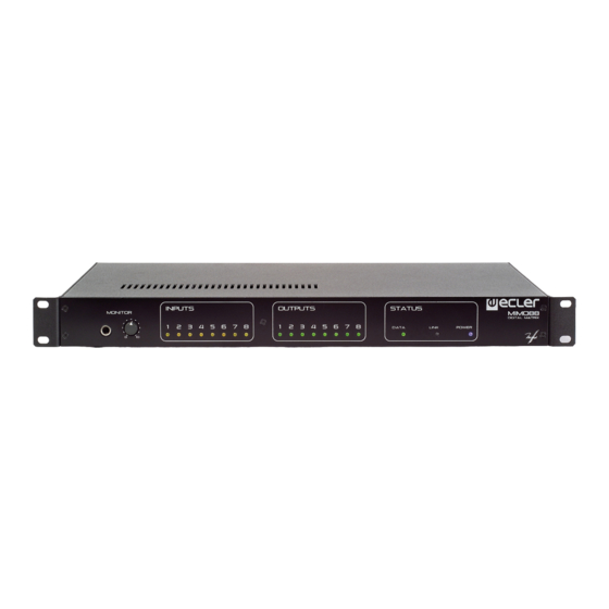
3.11. Front panel controls and LED indicators The following elements are available on the MIMO88 front panel: MONITOR output (1) (marked with a headphones symbol): it produces the same monitoring signal already available via the rear panel screw terminal block, but here on a ¼" TRS jack and with a rotary volume control (2 ) for listening through headphones. -
Página 9: Function List
5. FUNCTION LIST 1. Headphones connection stereo jack 2. Volume control for the headphones output, VOL 3. Input signal indicators, INPUTS 4. Output signal indicators, OUTPUTS 5. Data traffic indicator, DATA 6. Link (with another unit) indicator, LINK 7. Power on indicator, POWER 8. -
Página 10: Instrucciones Importantes De Seguridad
Explicación de los Símbolos Gráficos El símbolo del relámpago con una flecha en la punta y dentro de un triangulo equilátero, tiene el propósito de alertar al usuario de la presencia de un voltaje peligroso y sin aislar dentro del aparato, y de una magnitud tal que puede constituir riesgo de descarga eléctrica para las personas. - Página 11 7. CARACTERÍSTICAS TÉCNICAS 8. DIAGRAMA DE BLOQUES Todos los datos están sujetos a variación debida a tolerancias de producción. ECLER S.A. se reserva el derecho de realizar cambios o mejoras en la fabricación o diseño que pudieran afectar las especificaciones.
-
Página 12: Nota Importante
Consolas de mensajes (paging) virtuales y físicas. Mezclador automático. La programación del MIMO88 se realiza mediante la aplicación EclerNet Manager*. Consulte el manual de la Aplicación EclerNet Manager para obtener más información. * La aplicación EclerNet Manager se encuentra disponible para su descarga en www.ecler.com. -
Página 13: Instalación
3.2. Conexión a red eléctrica y encendido El MIMO88 funciona con tensión alterna de 90 a 264V y 47 a 63 Hz. Este aparato equipa una fuente de alimentación sobredimensionada capaz de adaptarse sin ningún tipo de ajuste a la tensión de red de cualquier país del mundo. -
Página 14: Puerto Ethernet De Programación Y Control
Maestro (MASTER) y la otra de Esclavo (SLAVE). El modo MASTER o SLAVE de cada unidad se ajusta mediante el selector (13) ubicado en el panel posterior. En instalaciones con un solo MIMO88 la posición del selector es indiferente. -
Página 15: Puertos Gpi De Control Remoto
3.8. Puertos GPI de control remoto MIMO88 dispone en su panel posterior de 8 entradas GPI (16) de control por tensión continua, 0 a 10 VDC. Cada una de estas entradas puede conectarse a un dispositivo físico externo (un potenciómetro, un cierre de contacto, una tensión continua 0-10V variable, etc.) y asociarse a una función del MIMO88, como por ejemplo:... -
Página 16: Controles E Indicadores Led Del Panel Frontal
3.11. Controles e indicadores LED del panel frontal MIMO88 dispone en su panel frontal de los siguientes elementos: Salida MONITOR (1) (marcada con símbolo de auriculares): se trata de la misma señal de monitoraje disponible en el panel posterior mediante regleta de tornillos, en este caso en formato jack TRS de ¼” y con un control de nivel giratorio (2) para la escucha mediante auriculares. -
Página 17: Lista De Funciones
5. LISTA DE FUNCIONES 1. Jack estéreo conexión auriculares 2. Control de volumen auriculares, VOL 3. Indicadores luminosos de señal de entrada, INPUTS 4. Indicadores luminosos de señal de salida, OUTPUTS 5. Indicador luminoso de tráfico de datos, DATA 6. Indicador luminoso de enlace con otra unidad, LINK 7. -
Página 18: Technical Characteristics
7. TECHNICAL CHARACTERISTICS 7. CARACTERÍSTICAS TÉCNICAS 7. CARACTERISTIQUES TECHNIQUES 7. TECHNISCHE DATEN 2x 32/64bit Sampling Rate 48kHz Latency IN to OUT <2.9ms (+1ms for 16x16) Converters Resolution 24bit AKM Dynamic Range AD:110dB, DA: 115dB Analog 8 Input/Output (expandable to 16x16) Terminal block (Symmetrical) 2 monitor output Terminal block (Symmetrical) - Página 19 Processing Input Level (x8) Range: from Off to 0 dB Mute: Yes Signal Polarity reverse: Yes Metering: VU+clip pre & post fader Output Level (x8) Range: from Off to 0 dB Mute: Yes Solo: Yes Signal Polarity reverse: Yes Metering: VU+clip pre & post fader Output Gain (x8) Range: from 0 to +6 dB Input Delay (x8)
- Página 20 Adjacent input / output channels Linked processing Matrix routing linked Mix Matrix Size: 8x8 (1-MIMO88) Size: 16x16 (2-MIMO88 with expan. link bus) Vol: Input, Output, Crosspoint Mute: Set/Clear individual, row, column, all Input /output Mono/stereo selector Meter: Input /output VU and clip...
-
Página 21: Block Diagram
8. BLOCK DIAGRAM 8. DIAGRAMA DE BLOQUES 8. DIAGRAMME DE BLOCS 8. BLOCKSCHATBILD... - Página 22 DISTRIBUIDOR EM PORTUGAL R. Sá de Figueiredo 6 – C 2790-233 Carnaxide Telef. (+351) 21 417 76 21 Fax. (+351) 21 030 00 31 Web: www.sislite.pt - email: geral.sislite@sislite.pt 50.0215.01.05...