
Manuales relacionados para Hunter Halcyon


Resumen de contenidos para Hunter Halcyon
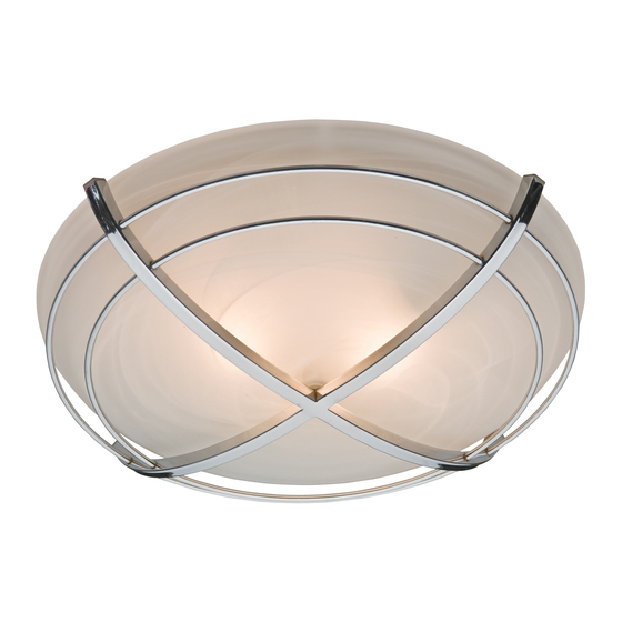
- Página 1 Halcyon Bath Ventilator with Light Owner’s Manual Model 81030 43034-01 20131201...
-
Página 2: Preventative Maintenance
TO REDUCE THE RISK OF FIRE, ELECTRIC SHOCK, OR INJURY TO PERSONS, OBSERVE THE FOLLOWING: 1. Use this unit only in a manner intended by the manufacturer. If Conditioning Engineers (ASHRAE), and the local code authorities. you have questions, contact the manufacturer. 5. -
Página 3: Before Installation
95044-01-000 Check all the parts. If damaged, call 95029-01-000 1-888-880-3267 77481-01-000 for replacements. 03242-07-133 98037-06-000 74508-03-133 77521-01 3/8” Cable C onnec to r 65219 98025-01 75184-01-133 Extra Screws 66002-01 NO TE: Strain relief cable connec tor must be installed. Not 77539-01 Included . - Página 4 Remove the motor/blower from the housing. Remove packing material. Remove the pre-loaded screw tip covers. Back out the pre-loaded screw tips until flush with the side of the housing. Remove the wiring cover screw. Remove the wiring cover. 43034-01 12/01/2013...
- Página 5 Pop out the first wiring access slug. Use second if Insert the strain relief into the housing and needed. secure with the washer. Choose Installation Option For New Construction - attaching to joist go to step A11, page 5 For New Construction - suspended between joists go to step B11, page 8 For Existing Construction - accessible from above go to step C11, page 11 For Existing Construction - accessible only from below go to step D11, page15...
- Página 6 Pull wires through the strain relief. Ground Black Green 2 Pin Bare Copper Whit e Black Main Switch 1 (AC In) Fan Moto r Whit e Whit e 3 Pin Ligh t Black Ligh t *Option Black Switch 2 (AC In) *Option F an &...
- Página 7 0 0 0 0 0 0 0 0 Reinstall the motor by inserting the tabs and pushing Connect wiring from the motor to the wiring cover up into position. Make sure the wires are not pinched plate. between the motor and the housing. Secure the motor by tightening the 2 screws.
- Página 8 New Construction – suspended between joists Slide the mounting rails into brackets. Position the correct depth mark at the bottom edge of the joist based on the thickness of your sheetrock. 1/8" Bit Mark position of screws by using holes as a template. Drill a hole in the center of each outline.
- Página 9 Tighten screws. Pull wires through the strain relief. Ground Black Green 2 Pin Bare Copper White Black Main Switch 1 (AC In) Fan Motor White White 3 Pin Black Light Light *Option Black Switch 2 (AC In) *Option Fan & Main Light Together Connect wires as shown.
- Página 10 Connect wiring from the motor to the wiring cover Reinstall the motor by inserting the tabs and pushing plate. up into position. Make sure the wires are not pinched between the motor and the housing. Secure the motor by tightening the 2 screws. Turn on the power source.
- Página 11 Existing Construction – accessible from above EXISTING FAN NO EXISTING FAN Remove an existing fan and check to make sure the Use the motor housing as a template to mark position. opening is large enough to accommodate the new motor housing (8”x 8.5”). Cut out an opening for the housing.
- Página 12 1/8" Bit Drill a hole in the center of each outline. Insert screws, leaving space between the screw head and the joist. Screws are not provided. Attach the rails onto the screws. Tighten screws. Connect 4” duct and vent to the outside. Tape joints. Pull wires through the strain relief.
- Página 13 Tighten the strain relief screws. Ground Black Green 2 Pin Bare Copper White Black Main Switch 1 (AC In) Fan Motor White White 3 Pin Black Light Light *Option Black Switch 2 (AC In) *Option Fan & Main Light Together Connect wires as shown.
- Página 14 Reinstall the motor by inserting the tabs and pushing Secure the motor by tightening the 2 screws. up into position. Make sure the wires are not pinched between the motor and the housing. O F F Turn on the power source. Test the motor.
- Página 15 Existing Construction – accessible only from below EXISTING FAN Remove an existing fan and check to make sure the Move the housing into position above the ceiling. opening is large enough to accommodate the new motor housing (8”x 8.5”). Attach existing ducting to duct connector. Tape joints. Pull wires through strain relief If ducting does not fit securely, an adapter may need to be purchased.
- Página 16 Ground Black Green 2 Pin Bare Copper Whit e Black Main Switch 1 (AC In) Fan Moto r Whit e Whit e 3 Pin Black Ligh t Ligh t *Option Black Switch 2 (AC In) *Option F an & Main Light Together Connect wires as shown.
- Página 17 O F F Test the motor. If the motor does not run, check the Turn on the power source. plug connection. Go to step on page 17 to attach grille . Attaching the Dome Assembly Connect wiring harness. Remove the thumbscrews. 43034-01 12/01/2013...
- Página 18 Remove the strain relief bracket screw. Position the strain relief bracket under the motor as shown. Insert the strain relief bracket’s dog-leg tab so that it Align posts A, B, C and D (stamped into motor housing) hooks over the lip of the motor. Reinstall the strain with posts A, B, C and D (stamped into light fixture).
- Página 19 Assemble the grille, glass dome, washer, and barrel Screw the dome assembly dome into position. nut as shown. Tighten the barrel nut “finger-tight.” NOTE: The washer must be oriented as shown. Complete. 43034-01 12/01/2013...
- Página 20 Trouble Shooting Problem: Fan does not come on. Solution: near the vents to feel the air movement. Problem: Light does not come on. Solution: Problem: Fan is noisy. Solution: If you need parts or service assistance, please call 1-888-880-3267 or visit us at our web site at http://www. hunterfan.com.
- Página 21 ABOVE FOR SUCH MOTORS OR OTHER PARTS. This warranty is voided if your Hunter bath exhaust fan is not purchased and installed in the U.S.A. This warranty excludes and does not cover defects, malfunctions or failures of any Hunter bath exhaust fan which were caused by repairs by persons not authorized by us, use of parts or accessories not authorized by us, mishandling, improper including failure to provide reasonable and necessary maintenance.
- Página 22 Halcyon Ventilador para baño con luz Manual del Propietario Modelo 81030 43034-02 20131201 43034-02 12/01/2013...
-
Página 23: Área De La Cocina
PARA REDUCIR EL RIESGO DE INCENDIO, CHOQUE ELÉCTRICO O LESIONES A PERSONAS, OBSERVE LO SIGUIENTE: 1. Utilice esta unidad sólo de la manera indicada por el fabricante. normas de seguridad, como las de la Asociación Nacional de Si tiene alguna pregunta, contacte con el fabricante. Protección contra Incendios (NFPA), la Asociación de Ingenieros Americanos en Calefacción y Aire acondicionado (ASHRAE), y los 2. -
Página 24: Antes De La Instalación
95044-01-000 95029-01-000 componentes. Si están daña- componentes. Si están daña- dos, llame al 1-888-880-3267 dos, llame al 1-866-405-3814 77481-01-000 para obtener un reemplazo. para obtener un reemplazo. 03242-07-133 98037-06-000 74508-03-133 77521-01 Conec tor de cable de 3/8” 65219 98025-01 75184-01-133 To rnillos adicionales 66002-01 NO TA: Debe estar instalado el... - Página 25 Retire el motor/soplador/soplador del alojamiento. Retire el material de embalaje. Retire las cubiertas de las puntas de tornillo precar- Retire las puntas de tornillo precargadas hasta que gadas. estén a nivel con el lado del alojamiento. Retire el tornillo de la cubierta del cableado. Retire la cubierta del cableado.
-
Página 26: Escoja La Opción De Instalación
Retire el primer tapón metálico de acceso del cab- Inserte el manguito de alivio de tensión (no se leado. Utilice el segundo si es necesario. incluye) en la caja y sujételo firmemente con una arandela. Escoja la opción de instalación Para construcción nueva - suspendido entre vigas, vaya al paso B11, página 48 Para construcción existente - accesible desde arriba, vaya al paso C11, página 51 Para construcción existente - accesible sólo desde abajo, vaya al paso D11,... - Página 27 Tienda los cables a través del manguito de alivio de tension. Tierra Negro Verde pasadores clavijas Cobre desnudo Blanco Negro Interruptor principal 1 (CA) Mot or del ventilador Blanco Blanco pasadores clavijas Negro Luz *Opción Negro Interruptor 2 (CA) *Opción Ventilador y luz principal junto s Conecte los alambres como se muestra.
- Página 28 0 0 0 0 0 0 0 0 Conecte el mazo de cables. NO PERMITA QUE EL Vuelva a instalar el motor/soplador introduciendo las MOTOR/SOPLADOR CUELGUE DEL MAZO DE pestañas y levantando a su posición. Asegúrese que CABLES. los alambres no se pellizquen entre el motor/soplador y el alojamiento.
-
Página 29: Construcción Nueva - Suspendido Entre Vigas
Construcción nueva – suspendido entre vigas Deslice los rieles de montaje en los soportes. Ubique la correcta marca de profundidad en el borde inferior de la viga, según el espesor de su plancha de yeso. 1/8" Bit Marque la posición de los tornillos utilizando los agu- Taladre un agujero en el centro de cada perfil. - Página 30 Apriete los tornillos. Tienda los cables a través del manguito de alivio de tension. Tierra Negro Verde pasadores clavijas Cobre desnudo Blanco Negro Interruptor principal 1 (CA) Mot or del ventilador Blanco Blanco pasadores clavijas Negro Luz *Opción Negro Interruptor 2 (CA) *Opción Ventilador y luz principal junto s Conecte los alambres como se muestra.
-
Página 31: C11 Ventilador Existente
Vuelva a instalar el motor/soplador introduciendo las Conecte el mazo de cables. NO PERMITA QUE EL pestañas y levantando a su posición. Asegúrese que MOTOR/SOPLADOR CUELGUE DEL MAZO DE los alambres no se pellizquen entre el motor/soplador CABLES. y el alojamiento. Asegure el motor/soplador apretando los 2 tornillos. -
Página 32: Construcción Existente - Accesible Desde Arriba
Construcción existente – accesible desde arriba VENTILADOR EXISTENTE SIN VENTILADOR EXISTENTE Retire el ventilador existente y asegúrese que la Utilice el alojamiento del motor/soplador como una abertura sea suficientemente grande para acomodar plantilla para marcar la posición. el alojamiento del motor/soplador nuevo (8 pulg. x 8 1/2 pulg.). - Página 33 broca de 1/8 de pulg . Taladre un agujero en el centro de cada perfil. Introduzca los tornillos, dejando espacio entre la cabeza del tornillo y la viga. No se proporcionan los tornillos. Fije los rieles con los tornillos. Apriete los tornillos. Conecte un ducto de 4”...
- Página 34 Apriete los tornillos del aliviador de tensiones. Tierra Negro Verde pasadores clavijas Cobre desnudo Blanco Negro Interruptor principal 1 (CA) Mot or del ventilador Blanco Blanco pasadores clavijas Negro Luz *Opción Negro Interruptor 2 (CA) *Opción Ventilador y luz principal junto s Conecte los alambres como se muestra.
- Página 35 Vuelva a instalar el motor/soplador introduciendo las Asegure el motor/soplador apretando los 2 tornillos. pestañas y levantando a su posición. Asegúrese que los alambres no se pellizquen entre el motor/soplador y el alojamiento. E N C E N D I D A P A G A D O Pruebe el motor/soplador.
-
Página 36: Construcción Existente - Accesible Sólo Desde Abajo
Construcción existente – accesible sólo desde abajo VENTILADOR EXISTENTE Retire el ventilador existente y asegúrese que la Mueva el alojamiento a su posición encima del techo. abertura sea suficientemente grande para acomodar el alojamiento del motor/soplador nuevo (8 pulg. x 8 1/2 pulg.). - Página 37 Tierra Negro Verde pasadores clavijas Cobre desnudo Blanco Negro Interruptor principal 1 (CA) Mot or del ventilador Blanco Blanco pasadores clavijas Negro Luz *Opción Negro Interruptor 2 (CA) *Opción Ventilador y luz principal junto s Conecte los alambres como se muestra. Instale la placa de cubierta del cableado.
-
Página 38: Fijación De La Rejilla
E N C E N D I D A P A G A D O Pruebe el motor/soplador. Si el motor/soplador no Encienda la fuente de alimentación. funciona, verifique la conexión del enchufe. Vaya al paso en la página 37 para Fijación de la rejilla Retire los tornillos de mano. - Página 39 Retire el tornillo del soporte del aliviador de tensiones. Coloque el soporte del aliviador de tensiones (3) debajo del motor como se muestra. Introduzca la pestaña en ángulo del soporte del alivi- Alinee los postes A, B, C y D (estampados en la caja del motor/soplador) con los postes A, B, C y D ador de tensiones para que se enganche en el borde (estampados en el artefacto de iluminación).
- Página 40 Ensamble la rejilla, domo de vidrio, arandela y man- Atornille el conjunto del domo en su posición. guito de tuerca como se muestra. Apriete el manguito de tuerca “a mano.” NOTA: Las arandelas deben estar orientadas como se muestra. Completo. 43034-02 12/01/2013...
-
Página 41: Solución De Problemas
Solución de problemas Problema: El ventilador no está operando. Solución: funcionando, coloque su mano cerca de los conductos de ventilación para sentir el movimiento del aire. Problema: La luz no funciona. Solución: Problema: El ventilador hace ruido. Solución: Si necesita repuestos o servicio, llame al 1-888-880-3267 o visite nuestro sitio web en http://www.hunterfan.com. -
Página 42: Garantía Limitada
Hunter: Si alguna pieza de su Extractor de aire para baño Hunter (con excepción de las lámparas de vidrio y las bombillas) falla en cualquier momento dentro de un año después de la fecha de compra debido a una falla de material o mano de obra, repararemos o, a nuestra elección, reemplazaremos la pieza defectuosa sin costo de partes y mano de obra realizada en...