Tabla de contenido
Publicidad
Idiomas disponibles
Idiomas disponibles
Enlaces rápidos
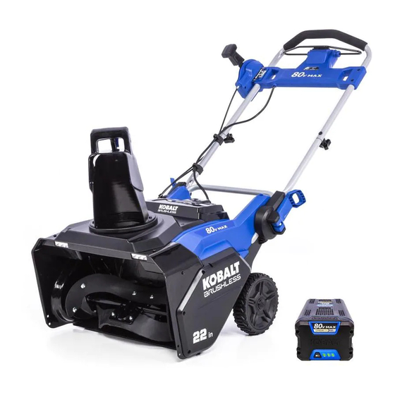
ITEM #1076663
80 V SNOW THROWER
MODEL #KSB 5080-06
Español p. 21
ATTACH YOUR RECEIPT HERE
Serial Number
Purchase Date
Questions, problems, missing parts? Before returning to your retailer, call our customer
service department at 1-888-3KOBALT (1-888-356-2258), 8 a.m. - 8 p.m., EST,
Monday - Friday.
PH18360
1
Publicidad
Capítulos
Tabla de contenido
Solución de problemas

Manuales relacionados para Kobalt KSB 5080-06


Resumen de contenidos para Kobalt KSB 5080-06
- Página 1 ITEM #1076663 80 V SNOW THROWER MODEL #KSB 5080-06 Español p. 21 ATTACH YOUR RECEIPT HERE Serial Number Purchase Date Questions, problems, missing parts? Before returning to your retailer, call our customer service department at 1-888-3KOBALT (1-888-356-2258), 8 a.m. - 8 p.m., EST, Monday - Friday.
-
Página 3: Tabla De Contenido
TABLE OF CONTENTS Product Specifications ....................2 Package Contents ....................... 3 Hardware Contents ...................... 4 Symbols ........................5 Safety Information ...................... 7 Preparation ........................ 9 Assembly Instructions ....................10 Operating Instructions ..................... 13 Care and Maintenance....................16 Troubleshooting ......................18 Warranty ......................... -
Página 4: Package Contents
PACKAGE CONTENTS PART DESCRIPTION PART DESCRIPTION Middle handle Chute deflector Quick-release lever Scraper Upper handle Drive belt cover Chute-rotation box Auger pulley Switch box Drive Belt Discharge chute Impeller Battery compartment cover Speed switch Safety switch button Wheels Bail lever Skid plates LED lights Battery... -
Página 5: Hardware Contents
HARDWARE CONTENTS (not shown actual size) Handle bolts Handle knobs Chute-rotation Discharge chute box screws screws Qty. 2 Qty. 2 Qty. 2 Qty. 3 Chute-rotation box screw nuts Qty. 2... -
Página 6: Symbols
SYMBOLS Some of the following symbols may be used on this product. Please study them and learn their mean- ing. Proper interpretation of these symbols will allow you to operate the product better and safer. SYMBOLS NAME DESIGNATION/EXPLANATION Volts Voltage Amperes Current Hertz... - Página 7 SYMBOLS The following signal words and meanings are intended to explain the levels of risk associated with this product. SYMBOL SIGNAL MEANING Indicates an imminently hazardous situation, which, if not DANGER avoided, will result in death or serious injury. Indicates a potentially hazardous situation, which, if not WARNING avoided, could result in death or serious injury.
-
Página 8: Safety Information
SAFETY INFORMATION WARNING Read and understand all instructions before using this product. Failure to follow all instructions listed below may result in electric shock, fire, and/or serious personal injury. The term “power tool” in all of the warnings listed below refers to your mains-operated (corded) power tool or battery-operated (cordless) power tool. - Página 9 • Stop the blade(s) when crossing gravel drives, walks, or roads. • For use only with Kobalt KB 580-06 battery and KRC 30-06 charger. • Read the operating and service instruction manual carefully. Be thoroughly familiar with the controls and the proper use of the equipment.
-
Página 10: General Safety Rules
SAFETY INFORMATION • Follow all charging instructions and do not charge the battery pack or appliance outside of the temperature range specified in the instructions. Charging improperly or at temperatures outside of the specified range may damage the battery and increase the risk of fire. •... -
Página 11: Assembly Instructions
ASSEMBLY INSTRUCTIONS WARNING • Do not allow familiarity with this product to make you careless. Remember that a careless fraction of a second is sufficient to inflict serious injury. • Do not use any attachments or accessories not recommended by the manufacturer of this product. The use of attachments or accessories not recommended can result in serious personal injury. - Página 12 ASSEMBLY INSTRUCTIONS 3. INSTALLING THE CHUTE-ROTATION BOX • Align the holes in the panel of the chute-rotation box (D) and the switch box (E). • Put the chute-rotation box screws (CC) through the holes. • Tighten the chute-rotation box screw nuts (EE) with a wrench (not included).
- Página 13 ASSEMBLY INSTRUCTIONS WARNING Always remove battery from your tool when you are assembling parts, making adjustments, cleaning, or when not in use. Removing battery will prevent accidental starting that could cause serious personal injury. 5a. TO INSTALL BATTERY PACK • Open the battery compartment cover (G).
-
Página 14: Operating Instructions
OPERATING INSTRUCTIONS 1a. POWERING ON Solution 1: 1. Press and hold the safety switch button (H). 2. Pull the bail lever (I) upward to the handle to start the snow thrower and then release the button. Solution 2: 1. Pull the bail lever (I) upward to the handle and hold it. 2. -
Página 15: Led Lights
OPERATING INSTRUCTIONS 2. LED LIGHTS • To turn on the LED lights (J) for night time snow removal, press the light switch (K). • To turn off the LED lights, press the light switch again. 3. SPEED SWITCH • Press the speed switch (S) towards the rabbit symbol for higher impeller speed and discharge distance in heavy conditions. -
Página 16: Operating Tips
OPERATING INSTRUCTIONS 5. ADJUSTING THE CHUTE DEFLECTOR Trigger You can adjust the chute deflector (M) up and down to change the throwing distance of the snow. • Squeeze and hold the trigger on the chute deflector. • Move the chute deflector up to increase the snow distance. -
Página 17: Care And Maintenance
CARE AND MAINTENANCE IMPORTANT: Always remove the battery from the tool before performing any maintenance on it. 1. REPLACING THE SCRAPER NOTE: The scraper is located at the bottom of the impeller housing. Ensure that the battery is not installed in the tool. •... -
Página 18: Replacing The Impeller
CARE AND MAINTENANCE 3. REPLACING THE IMPELLER 4 sets of nuts and bolts on the middle steel plate • Remove the 4 sets of nuts and bolts on the middle steel plate. • Remove the 4 sets of nuts and bolts on each side. -
Página 19: Troubleshooting
TROUBLESHOOTING If you still have questions or an unresolved issue after going through this troubleshooting guide, or just want to speak to a Kobalt product expert, please call our Kobalt customer service department at 1-888-356-2258. PROBLEM POSSIBLE CAUSE CORRECTIVE ACTION The handle is not 1. -
Página 20: Warranty
WARRANTY 5-YEAR LIMITED WARRANTY This 80 V Lithiuim-Ion snow thrower is warranted to the original purchaser from the original purchase date for five (5) years subject to the warranty coverage described herein. This 80 V Lithiuim-Ion snow thrower is warranted for the original user to be free from defects in material and workmanship. -
Página 21: Replacement Parts List
REPLACEMENT PARTS LIST For replacement parts, call our customer service department at 1-888-356-2258. PART DESCRIPTION PART # Handle bolts 322022607 Handle knobs 34113877-1 Chute-rotation box screws 322012607 Discharge chute screws 322071495 Chute-rotation box screw nuts 3220439 Impeller 342051495 Scraper 341271495 Drive belt 342011495 Skid plates... -
Página 22: Equipo Quitanieve De 80 Voltios
ARTÍCULO #1076663 EQUIPO QUITANIEVE DE 80 VOLTIOS MODELO #KSB 5080-06 ADJUNTE SU RECIBO AQUÍ Número de serie Fecha de compra ¿Preguntas, problemas, piezas faltantes? Antes de volver a la tienda, llame a nuestro Departamento de Servicio al Cliente al 1-888-3KOBALT (1-888-356-2258), de lunes a... -
Página 23: Especificaciones Del Producto
ÍNDICE Especificaciones del producto ����������������������������������������������������������������������������������� 22 Contenido del paquete ���������������������������������������������������������������������������������������������� 23 Aditamentos ��������������������������������������������������������������������������������������������������������������� 24 Símbolos ������������������������������������������������������������������������������������������������������������������� 25 Información de seguridad ������������������������������������������������������������������������������������������ 27 Preparación �������������������������������������������������������������������������������������������������������������� 29 Instrucciones para el ensamblaje ������������������������������������������������������������������������������ 30 Instrucciones de uso ������������������������������������������������������������������������������������������������� 33 Cuidado y mantenimiento ������������������������������������������������������������������������������������������ 37 Detección de problemas ��������������������������������������������������������������������������������������������... -
Página 24: Contenido Del Paquete
CONTENIDO DEL PAQUETE PIEZA DESCRIPCIÓN PIEZA DESCRIPCIÓN Manija central Deflector del canal Palanca de liberación rápida Raspador Manija superior Cubierta de la correa de transmisión Caja de rotación del conducto Polea de la barrena Caja del interruptor Correa de transmisión Canal de descarga Impulsor Cubierta del compartimiento de... -
Página 25: Aditamentos
ADITAMIENTOS (no se muestran en el tamaño real) Pernos de la manija Perillas de la manija Tornillos de la caja de Tornillos del conducto rotación del conducto de descarga Cantidad: 2 Cantidad: 2 Cantidad: 2 Cantidad: 3 Tuercas para tornillos de la caja de rotación del conducto Cantidad: 2... -
Página 26: Símbolos
SÍMBOLOS Algunos de los siguientes símbolos pueden ser usados en este producto� Obsérvelos y aprenda su significado. La interpretación correcta de estos símbolos permite una operación mejor y más segura. SÍMBOLOS NOMBRE DESIGNACIÓN/EXPLICACIÓN Voltios Voltaje Amperios Corriente Hercios Frecuencia (ciclos por segundo) Vatio hora Capacidad de almacenaje de energía Amperio hora... -
Página 27: Significado
SÍMBOLOS Las siguientes palabras de señalizacion y sus significados tienen el objeto de explicar los niveles de riesgo relaciondos con este producto� SÍMBOLO SEÑAL SIGNIFICADO Indica una situación de peligro inminente que, si no es preveni- PELIGRO da, causará la muerte o lesiones severas� Indica una situación de peligro potencial que, si no es preveni- ADVERTENCIA da, podría causar la muerte o lesiones severas�... -
Página 28: Información De Seguridad
INFORMACIÓN DE SEGURIDAD ADVERTENCIA Lea y asegúrese de comprender todas las instrucciones antes de usar este producto� Si no se siguen todas las instrucciones mencionadas a continuación, pudieran producirse descargas eléctricas, incendios y/o lesiones severas� El término “herramienta eléctrica” empleado en todos los avisos de advertencia enumerados abajo se refiere a las herramientas eléctricas de cordón (alámbricas) y de baterías (inalámbricas). - Página 29 • Detenga las cuchillas cuando cruce entradas, caminos o carreteras con gravilla� • Use solo con la batería Kobalt KB 580-06 y el cargador KRC 30-06� • Lea cuidadosamente el manual de instrucciones de funcionamiento y servicio� Familiarícese por completo con los controles y el uso adecuado de este equipo�...
-
Página 30: Normas Generales De Seguridad
INFORMACIÓN DE SEGURIDAD • Cuando el paquete de baterías no está en uso, aléjelo de objetos metálicos, como sujetapapeles, monedas, llaves, clavos, tornillos u otros objetos metálicos pequeños que pudieran crear una conexión entre los terminales� Es posible que conectar los terminales de la batería entre sí produzca quemaduras o un incendio�... -
Página 31: Instrucciones Para El Ensamblaje
INSTRUCCIONES PARA EL ENSAMBLAJE ADVERTENCIA • No permita que la familiaridad con este producto lo vuelva descuidado� Recuerde que un descuido de una fracción de segundo es suficiente para provocar lesiones graves. • No utilice ningún acoplamiento o accesorio que no sea recomendado por el fabricante de este producto�... -
Página 32: Instalación Del Conducto De Descarga
INSTRUCCIONES PARA EL ENSAMBLAJE 3. INSTALACIÓN DE LA CAJA DE ROTACIÓN DEL CONDUCTO • Alinee los orificios en el panel de la caja de rotación del conducto (D) y la caja del interruptor (E)� • Coloque los tornillos de la caja de rotación del conducto (CC) en los orificios. - Página 33 INSTRUCCIONES PARA EL ENSAMBLAJE ADVERTENCIA Siempre retire el paquete de baterías de la herramienta cuando no esté en uso o cuando esté ensamblando las piezas, realizando ajustes o limpiándolo� La extracción de la batería evitará que se produzca un arranque accidental, lo que podría causar graves lesiones personales� 5a.
-
Página 34: Instrucciones De Uso
INSTRUCCIONES DE USO 1a. ENCENDIDO Solución 1: 1� Mantenga presionado el botón del interruptor de seguridad (H)� 2� Jale la palanca de agarre (I) hacia arriba de la manija para arrancar el equipo quitanieve y luego suelte el botón� Solución 2: 1�... -
Página 35: Luces Led
INSTRUCCIONES DE USO 2. LUCES LED • Para encender las luces LED (J) para quitar nieve de noche, presione el interruptor de luz (K)� • Para apagar las luces LED, presione el interruptor de luz nuevamente� 3. INTERRUPTOR DE VELOCIDAD •... -
Página 36: Ajuste Del Deflector Del Conducto
INSTRUCCIONES DE USO 5. AJUSTE DEL DEFLECTOR DEL CONDUCTO Puede ajustar el deflector del conducto (M) hacia Gatillo arriba o hacia abajo para cambiar la distancia de soplado de nieve� • Mantenga presionado el gatillo del deflector del conducto� • Mueva el deflector del conducto hacia arriba para aumentar la distancia de la nieve�... - Página 37 INSTRUCCIONES DE USO • Cuando trabaje sobre guijarros, gravilla o superficies no pavimentadas, evite arrojar materiales sueltos de la superficie junto con la nieve presionando la manija hacia abajo o ajustando las zapa- tas para elevar el raspador en la base de la unidad por sobre los guijarros o la gravilla� •...
-
Página 38: Cuidado Y Mantenimiento
CUIDADO Y MANTENIMIENTO IMPORTANTE: siempre retire la batería de la herramienta antes de realizar cualquier tarea de mantenimiento� 1. REEMPLAZO DEL RASPADOR NOTA: el raspador se ubica en la parte inferior de la carcasa del impulsor� Asegúrese de que la batería no esté... -
Página 39: Reemplazo De Las Zapatas
CUIDADO Y MANTENIMIENTO 3. REEMPLAZO DEL IMPULSOR 4 conjuntos de tuercas y pernos en la placa de acero central • Retire los 4 conjuntos de tuercas y pernos en la placa de acero central� • Retire los 4 conjuntos de tuercas y pernos de cada lado�... -
Página 40: Solución De Problemas
Si continua teniendo dudas o algún otro asunto sin resolver tras haber consultado esta guía de reso- lución de problemas o simplemente desea hablar con un experto en productos Kobalt, llame al servi- cio de atención al cliente de Kobalt al 1-888-356-2258�... -
Página 41: Garantía
GARANTÍA GARANTÍA DE REPARACIÓN DE 5 AÑOS Este equipo quitanieve de iones de litio de 80 voltios está garantizado para el comprador original desde la fecha de compra original durante cinco (5) años y está sujeto a la cobertura de garantía que aquí se describe�... -
Página 42: Lista De Piezas De Repuesto
LISTA DE PIEZAS DE REPUESTO Para encargar piezas de repuesto, llame a nuestro Departamento de Servicio al Cliente al 1-888-356-2258� PIEZA DESCRIPCIÓN PIEZA # Pernos de la manija 322022607 Perillas de la manija 34113877-1 Tornillos de la caja de rotación del conducto 322012607 Tornillos del conducto de descarga 322071495...