Tabla de contenido
Publicidad
Idiomas disponibles
Idiomas disponibles
Enlaces rápidos
ATS1100/1105 8-Area LCD RAS Installation
Sheet
EN DA DE ES
FI
FR
1
(1)
J2
J3
EN: Installation Sheet
Mounting the unit
Please make sure the keypad is mounted on a flat surface, in
order to prevent any incorrect tamper switch actuations.
Attach the mounting box using screws. Secure the PCB with
the screw supplied. Secure the keypad cover with the screw
supplied.
When a pry-off tamper is required, use a screw in the back of
the keypad (see Figure 1, item 2).
Connecting the keypad to a control panel
Figure 1, item 1: Refer to the ATS control panel installation
guide for instructions.
LEDs
•
Rx: LED flashes to indicate polling data is being received
on the system data bus from the ATS control panel. If the
LED does not flash the control panel is not operational or
the data bus is faulty (usually cabling).
•
Tx: LED flashes to indicate the arming station (RAS) is
replying to polling from the ATS control panel. If the Rx
(Rx0) LED flashes but the Tx (Tx0) LED does not, the
arming station (RAS) is not programmed to be polled in
the control panel or is addressed incorrectly.
© 2019 UTC Fire & Security Americas Corporation, Inc.
IT
NL NO PL PT SV
Rx
Tx
(2)
(3)
1 2 3 4
(4)
1 2 3 4
SW2
2
ON
SD
ON
1
2 3 4
1
RAS 1
ON
SD
ON
1
2 3 4
1
RAS 5
ON
SD
ON
1
2 3 4
1
RAS 9
ON
SD
ON
1
2 3 4
1
RAS 13
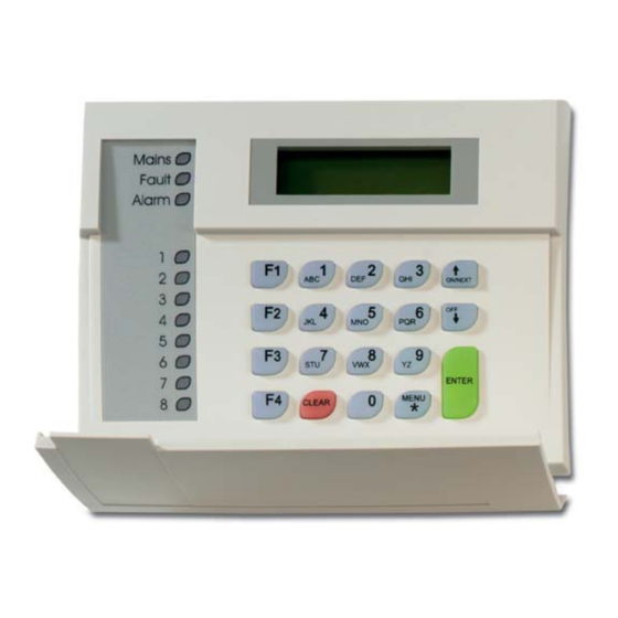
LED Indications on keypad
•
Area: 8 red LEDs illuminate when area 1–8 (or 9–16) are
armed. Will blink (armed) or flash (disarmed) on alarm.
•
Mains: Green LED illuminates if 230 VAC mains power is
available.
•
Alarm: Red LED illuminates on any alarm in an area
assigned to the keypad.
•
Fault: Yellow LED illuminates on faults in the system.
Comms connections
See Figure 1, terminal J3.
•
+12, 0V: Power supply. If the distance between the arming
station and the control panel does not exceed 100 m, then
the arming station can be powered using the Comms +
and − from the control panel. Otherwise use AUX PWR
from DGPs or an auxiliary power supply.
•
D+, D−: Data positive and data negative connection of the
data bus.
Remote units can be up to 1.5 km from the ATS control
panel.
•
IN: A request to exit button (normally open, momentary
push-button switch) can be connected across "IN" and "−".
When pressed, this button controls the request to exit
function.
•
OUT: Open collector output, 50 mA maximum. It is the first
output of the output control group that is assigned to this
arming station.
1 / 1
SW1
SD
ON
SD
ON
SD
2 3 4
1
2 3 4
1
2 3 4
RAS 2
RAS 3
RAS 4
SD
ON
SD
ON
SD
2 3 4
1
2 3 4
1
2 3 4
RAS 6
RAS 7
RAS 8
SD
ON
SD
ON
SD
2 3 4
1
2 3 4
1
2 3 4
RAS 10
RAS 11
RAS 12
SD
ON
SD
ON
SD
2 3 4
1
2 3 4
1
2 3 4
RAS 14
RAS 15
RAS 16
P/N 1052492 (ML) • REV C • ISS 24JUN19
Publicidad
Tabla de contenido

Resumen de contenidos para Interlogix ATS1100
- Página 1 ATS1100/1105 8-Area LCD RAS Installation Sheet EN DA DE ES NL NO PL PT SV 2 3 4 2 3 4 2 3 4 2 3 4 RAS 1 RAS 2 RAS 3 RAS 4 2 3 4 2 3 4...
-
Página 2: Tilslutning Af Ras'en Til En Centralenhed
Readers connections (ATS1105 only) See Figure 1, terminal J2. Contact information +5 V supply and data connections for ATS magnetic card www.utcfireandsecurity.com or www.interlogix.com readers (ATS1105 only). For customer support, see www.utcfssecurityproducts.eu • 1: D1/D Read data pulse / Wiegand D1 line •... -
Página 3: Led-Visninger På Betjeningspanel
• Tx: LED blinker for at angive, at RAS’en reagerer på SW2-4, TERM polling fra ATS-central. Hvis RX LED'en blinker, men Tx OFF: Ikke sidste enhed på databussen. LED'en ikke blinker, er RAS’en ikke programmeret til at polles i centralenheden eller RAS’en har forkert adresse. ON: Terminering af databussen, hvis denne RAS er den sidste enhed på... -
Página 4: Montage Des Geräts
Datenbusverbindungen + und − von der Kontaktinformation Einbruchmeldezentrale mit Spannung versorgt werden. Verwenden Sie anderenfalls den Anschluss AUX PWR www.utcfireandsecurity.com eller www.interlogix.com von den AMEs oder eine Nebenmelderversorgung. For kundesupport se www.utcfssecurityproducts.dk • D+, D–: Positive und negative Datenverbindung des Datenbusses. - Página 5 • 3: GND (0V) • 4: +5 V Kontaktinformationen • 5: +12 V www.utcfireandsecurity.com oder www.interlogix.com Zusätzliche Funktionalität Kontaktinformationen für den Kundendienst finden Sie unter www.utcfssecurityproducts.de • Zum Anpassen des LCD-Kontrasts – Drücken Sie Menü * und oder .
-
Página 6: Conexiones Comms
• Alimentación: Cuando la alimentación de 230 V CC está SW2-4, TERM conectada, se ilumina un LED verde. OFF: No es el último dispositivo del bus de datos. • Alarma: En caso de que se produzca una alarma, sea del ON: Termina el bus de datos si esta estación RAS es el último tipo que sea, en un área asignada al teclado, se ilumina dispositivo del bus de datos. -
Página 7: Käyttönäppäimistön Merkkivalot
AUX PWR - liitäntää tai lisäteholähdettä. Información de contacto • D+, D−: Dataväylän positiivinen ja negatiivinen dataliitäntä. www.utcfireandsecurity.com o www.interlogix.com Para acceder al servicio técnico, consulte Lisälaitteet voivat olla jopa 1,5 km:n päässä ATS- www.utcfssecurityproducts.es keskuslaitteesta. •... -
Página 8: Fr: Fiche D'installation
(lisää) ja (vähentää) keräyspisteeseen. Lisätietoja sivuilla www.recyclethis.info Tekniset tiedot Yhteystiedot Käyttöjännite 10,5–13,8 V , 12 V nom. www.utcfireandsecurity.com tai www.interlogix.com Maksimivirrankulutus 185 mA Koodiyhdistelmät: Tietoja asiakastuesta on osoitteessa 4 numeroa 10 000 www.utcfssecurityproducts.fi 9 numeroa... -
Página 9: Caractéristiques Techniques
SW2-1, A Groupes 9 à 16 grâce aux connexions Comms + et − de la centrale. Utilisez sinon la connexion AUX PWR des DGP ou une OFF (désactivé) : Les voyants lumineux affichent l’état des alimentation électrique auxiliaire. groupes 1 à 8. •... -
Página 10: It: Istruzioni D'installazione
Vedi anche la guida di installazione della centrale ATS. Pour nous contacter www.utcfireandsecurity.com ou www.interlogix.com • Pour contacter l'assistance clientèle, voir Rx: Il LED lampeggia per indicare che il bus dati del sistema riceve i dati di interrogazione dalla centrale ATS. -
Página 11: Funzionalità Supplementare
Per regolare il contrasto del Display – Premere Menu * e oppure Informazioni di contatto • Per regolare il volume del ciaclino, premere Clear e per www.utcfireandsecurity.com o www.interlogix.com aumentare e per diminuire Per l'assistenza clienti, vedere www.utcfssecurityproducts.it Specifiche NL: Installatieblad... - Página 12 • Tx: De LED knippert om aan te geven dat het ON: De verlichting van het bediendeel blijft altijd aan. gebruikersinterface (GI) reageert op het pollen van het ATS -controlepaneel. Als de Rx-LED wel knippert maar de SW2-3, C Magnetisch kaartformaat (alleen ATS1105) Tx-LED niet, dan is het gebruikersinterface (GI) niet OFF: ATS-formaat.
-
Página 13: Led-Indikatorer På Betjeningspanelet
«IN» og «−». Når denne trykkes, kontrollerer den åpne-funksjonen. Contact informatie • OUT: Åpen kollektor-utgang, maksimalt 50 mA. Det er den www.utcfireandsecurity.com of www.interlogix.com første utgangen til utgangskontrollgruppen som er tildelt dette betjeningspanelet. Voor klantenondersteuning, zie www.utcfssecurityproducts.nl Dip-bryterinnstillinger for BP NO: Installasjonsark Figur 1, enhet 3: SW1 Dip-brytere. -
Página 14: Pl: Instrukcja Instalacji
4: +5 V www.recyclethis.info • 5: +12 V Kontaktinformasjon Ekstra funksjonalitet www.utcfireandsecurity.com eller www.interlogix.com • Juster LCD-kontrast, ved å trykke på Menu *-knappen For kundestøtte, se www.utcfssecurityproducts.no samtidig som pil opp/ned-tastene • For å justere lydstyrken til summeren taster du Clear og ... -
Página 15: Połączenia Komunikacyjne
Połączenia komunikacyjne Podłączenia czytników (tylko ATS1105) Patrz rysunek 1, zacisk J3. Patrz rysunek 1, zacisk J2. +12, 0V: Zasilacz. Jeśli odległość między stacją prądu stałego i połączenia danych do czytników • Zasilanie +5 zazbrajania i centralą nie przekracza 100 m, wówczas kart magnetycznych ATS (tylko ATS1105). -
Página 16: Pt: Ficha De Instalação
IN: Um botão de pedido de saída (normalmente aberto, botão de pressão) pode ser ligado entre “IN” e “−“. Ao ser www.utcfireandsecurity.com lub www.interlogix.com premido, este botão controla a função de pedido para sair. Informacje na temat pomocy technicznej można znaleźć na •... -
Página 17: Especificações
ATS-centralapparaten. Informação de contacto • IN: En Öppna-knapp (vanligen öppen, momentan tryckknappsbrytare) kan anslutas mellan ”IN” och ”−”. När www.utcfireandsecurity.com ou www.interlogix.com den trycks in kontrollerar den här knappen funktionen Utgångsförfrågan. Para assistência ao cliente, consulte www.utcfssecurityproducts.eu P/N 1052492 (ML) • REV C • ISS 24JUN19... -
Página 18: Information Om Regler Och Föreskrifter
För mer information, centralapparat. se: www.recyclethis.info Läsaranslutningar (endast ATS1105) Kontaktuppgifter Se figur 1, plint J2. www.utcfireandsecurity.com eller www.interlogix.com tillförsel och dataanslutningar för ATS +5 V Kundsupport finns på www.utcfssecurityproducts.se magnetkortsläsare (endast ATS1105 ). • 1: D1/D Läs datapuls/Wiegand D1-linje •...