Tabla de contenido
Publicidad
Idiomas disponibles
Idiomas disponibles
Enlaces rápidos
Publicidad
Tabla de contenido

Manuales relacionados para Steren MUL-600


Resumen de contenidos para Steren MUL-600
-
Página 2: Multímetro Profesional De Lujo Con Interfase Para Pc
Multímetro profesional de lujo con interfase para PC. Por favor, revíselo completamente para estar seguro de cómo utilizar apropiadamente el producto. Para apoyo, compras y todo lo nuevo que tiene Steren, visite nuestro sitio web: www.steren.com La información que se muestra en este manual sirve únicamente como referencia sobre el producto. -
Página 3: Información De Seguridad
Información de seguridad Este medidor cumple con los estándares IEC1010: en grado de contaminación 2, Categoría de sobre voltaje (CAT. II 1 000 V, CAT. III 600 V) y doble aislamiento. CAT. II Nivel Local, en aplicaciones de equipo portátil, con pequeños voltajes transitorios. - Página 4 - Cuando el medidor trabaja hacia un voltaje efectivo sobre 60 V --- o 30 V ~ rms, especial cuidado debe tenerse para no sufrir un choque eléctrico. - Utilice las terminales, funciones y rango adecuados para sus mediciones. - No use o almacene el medidor en un ambiente de alta temperatura, humedad, explosivo, infl...
- Página 5 El multímetro digital MUL-600 combina la opción de ser un multímetro Auto Rango y a la vez un multímetro de opción manual, con una lectura máxima de 3999. Su estructura adopta un avanzado diseño de técnica de co-inyección que provee un aislamiento superior.
- Página 6 ACCESORIOS 1. Puntas de prueba. 2. Puntas con caimán. 3. Conector termopar. 4. Cable de interfaz RS232C. 5. Batería de 9 V ---...
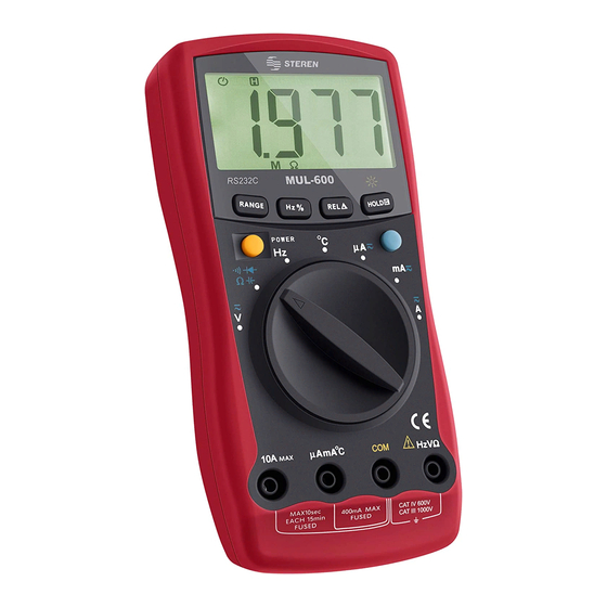
- Página 7 PARTES 1. Pantalla LCD 2. Botones de funciones Encendido Botón azul: Cambia la función de medición requerida en caso de que haya más de una en la posición del interruptor giratorio. RANGE: Selección de rango auto rango o manual. Hz %: Contador de frecuencia y de función de ciclo. REL: Establece la medición actual como referencia, sustrae ese valor almacena- do del valor de la siguiente medición y despliega el resultado.
-
Página 9: Funciones De Los Botones
FUNCIONES DE LOS BOTONES La tabla siguiente indica la información de los botones de funciones. Botón Función de medir Ejecución de la operación Cualquier posición del Oprima el botón de encendido, vuelva a oprimir Encendido interruptor para apagar. El cambio entre el voltaje CA(~) y CD(---) el medidor sonará, CD(---) está... - Página 10 Botón Función de medir Ejecución de la operación 1. Presionar inicio del contador de frecuencia; el medidor sonará. 2. Presione de nuevo para entrar al modo de función de ciclo; el medidor sonará. 3. Presione de nuevo para regresar al modo de contador de frecuencia, el medidor sonará.
-
Página 11: Símbolos En La Pantalla
SÍMBOLOS EN LA PANTALLA... - Página 12 Número Símbolo Signifi cado Indicador de corriente alterna. El valor desplegado es el valor medio. TRMS No aplica El medidor está en modo auto rango, modo en el cual el AUTO medidor automáticamente selecciona el mejor rango con la mejor resolución. Salida de datos, éstos estarán siempre sobre la pantalla LCD, pero la salida de datos está...
- Página 13 Número Símbolo Signifi cado Ω: Ohm, unidad de resistencia Resistencia kΩ: kilo ohm. 1 x 10³ o 1000 ohms Megaohm. 1 x 10⁶ o 1000000 ohms F: Farad. La unidad de capacitancia F, μF, nF μF: Microfaradios. 1 x 10⁻⁶ o 0,000001 faradios nF: Nano faradios 1 x 10⁻⁹ o 0,000000001 faradios Hertz: unidad de frecuencia en ciclos/segundo 12-16...
-
Página 14: Funciones Extra
FUNCIONES EXTRA Operación del modo HOLD Para eliminar el riesgo de un choque eléctrico, no utilice el modo HOLD hasta determinar si los circuitos están sin energía. El modo HOLD no captura medidas inestables o ruido y es aplicable en todas las funciones de medición. - Presione HOLD, para entrar en el modo HOLD;... -
Página 15: Uso Del Modo De Valor Relativo
Uso del modo de Valor Relativo El modo valor relativo aplica a todas las funciones de medición excepto medición de frecuencia/ciclo de trabajo. Éste sustrae un valor almacenado del valor de la presente medición y despliega el resultado. Por ejemplo, si el valor almacenado es 20 V y el valor presente medido es 22V, la lectura deberá... -
Página 16: Iluminación De La Pantalla
Iluminación de la pantalla - Presione HOLD por más de 2 segundos para encender la iluminación de la pantalla. - Presione HOLD de nuevo por más de 2 segundos para apagar la iluminación. Modo inactivo Para preservar la vida de la batería, el medidor se apaga automáticamente si usted dejó... -
Página 17: Modo De Uso
MODO DE USO Instalar/cambiar la batería Asegúrese de remover las puntas antes de quitar la tapa del medidor. 1. Apague el medidor y remueva todas las conexiones de las terminales. 2. Quite el tornillo y extraiga el compartimento batería, posteriormente, remueva la tapa. 3. -
Página 18: Reemplazo De Fusible
Reemplazo de fusible -Para evitar choque eléctrico, sacudida por arco voltaico o daño a su persona o al medidor, utilice sólo el fusible especifi cado de acuerdo con el siguiente procedimiento. 1. Apague el medidor y remueva todas las conexiones del mismo. 2. -
Página 19: Interruptor Giratorio
Interruptor giratorio La tabla siguiente indica la información acerca de las posiciones del interruptor. Posición del Función interruptor giratorio • Medición de Voltaje de CD (---) rango de 400mV a 100 V--- ó Medición de voltaje de CA (~) rango de 4 a 750 V~ Prueba de continuidad. -
Página 20: Rangos De Medición
Rangos de Medición Un rango de medición determina el valor más alto que el medidor puede calcular. La mayoría de las funciones del medidor tienen más de un rango. A. Selección de un Rango de Medición Iniciar en el rango de medición correcto es importante. -Si el rango es demasiado bajo para la entrada, el medidor desplegará... - Página 21 El medidor tiene prefi jado el modo de medición de auto rango. Cuando el medidor está en el modo de auto rango, la palabra AUTO se visualiza en la pantalla. 1. Para entrar al modo rango manual presione RANGE. El medidor entra en el modo de rango manual y apaga el modo AUTO.
-
Página 22: Operación
OPERACIÓN - Siempre que termine sus mediciones, desconecte la conexión entre las puntas de prueba y el circuito bajo prueba, posteriormente remueva las puntas de prueba de la entrada del medidor. a) Medición de Voltaje de CD (---) y de CA En caso de que haya más de una función en la posición del interruptor giratorio, presione el botón azul para seleccionar la función de medición requerida. -
Página 23: Medición De Resistencia, Continuidad, Diodos Y Capacitancia
b) Medición de Resistencia, Continuidad, Diodos y Capacitancia Los rangos de resistencia son 400Ω / 4kΩ / 40kΩ / 400kΩ / 4MΩ / 40MΩ. Los rangos de medición de capacitancia son 40nF / 400nF / 4μF / 40μF / 100μF. 1. - Página 24 - Las puntas de prueba pueden sumar un error de 0,1 a 0,2 en la medición de resistencia. Para obtener lecturas de precisión en mediciones de resistencia baja, esto es en el rango de 400Ω, cortocircuitar las terminales de entrada de antemano utilizando el botón de la medición de función relativa REL automáticamente substraerá...
-
Página 25: Medición De Frecuencia
c) Medición de Frecuencia El rango de medición es de 10 Hz a 10 MHz. Para medir frecuencia, conecte el medidor como sigue: 1. Inserte la punta roja dentro de la terminal HzVΩ y la negra dentro de la terminal COM. 2. -
Página 26: Medición Del Ciclo De Trabajo
d) Medición del Ciclo de Trabajo La medición del ciclo de trabajo es 0,1 % a 99,9%. 1. Fije el medidor para medir frecuencia. 2. Para seleccionar el ciclo de trabajo, presione Hz% hasta que el símbolo % se muestre en la pantalla. -
Página 27: Medición De Temperatura
e) Medición de Temperatura El rango de medición de temperatura es -40 °C a 1000 °C. 1. Inserte la punta roja del probador de temperatura dentro de la terminal μAmA°C y la negra dentro de la terminal COM. 2. Fije el interruptor giratorio a °C. 3. - Página 28 f) Medición de Corriente ACA (A~) y ACD (A ---) Nunca intente medir corriente en un circuito cuando el voltaje de circuito abierto entre el circuito y tierra es mayor de 600 V. Si el fusible se quema durante la medición, el medidor puede estar dañado o el operador puede lastimarse a sí...
- Página 29 3. Posicione el interruptor giratorio en μA, mA o A, de acuerdo con sus necesidades. 4. El medidor entrará al modo de medición de CD (---) predeterminadamente. Para cambiar entre CD (---) y CA (~) presione el botón azul. El valor desplegado de CA (~) es el valor efectivo de la onda senoidal (valor de respuesta principal).
-
Página 30: Especificaciones De Medición
ESPECIFICACIONES DE MEDICIÓN Voltaje de CD (---) Rango Resolución Exactitud Protección contra sobrecarga 400 mV 0,1 mV ±(0,8% + 3) 1 mV 1000 VCD 40 V 10 mV ±(0,8% + 3) 750 VCA rms continuos 400 V 100 mV 1000 V ±(1% + 3) Voltaje de CA (~) Rango... -
Página 31: Resistencia
Resistencia Rango Resolución Exactitud Protección contra sobrecarga 400 Ω 0,1 Ω ±(1,2% + 2) 4 k Ω 1 Ω 40 k Ω 10 Ω ±(1% + 2) 1000 Vp 400 k Ω 100 Ω 4 M Ω 1 k Ω ±(1,2% + 2) 40 M Ω... -
Página 32: Capacitancia
Capacitancia Rango Resolución Exactitud Protección contra sobrecarga Medición en modo REL 40 nF 10 pF ±(3% + 10) 400 nF 100 pF 1000 Vp 4 μF 1 nF ±(3% + 5) 40 μF 10 nF 100 μF 100 nF ±(4% + 5) Frecuencia Rango Señal requerida... -
Página 33: Ciclo De Trabajo
Temperatura Rango Resolución Exactitud Protección contra sobrecarga -40°C a 0°C ±(3% + 10) -40°C a 1000°C 1°C 0°C a 400°C ±(1% + 7) 400°C a 1000°C ±(2% + 10) Corriente de CD (---) Rango Resolución Exactitud Protección contra sobrecarga 400 μA 0,1 μA ±(1% + 2) 4000 μA... - Página 34 Corriente de CA (~) Rango Resolución Exactitud Protección contra sobrecarga 400 μA 0,1 μA ±(1,5% + 5) 4000 μA 1 μA Fusible de cerámica 0,5 A 250 V, tipo 40 mA 0,01 mA rápido 5 x 20 mm ±(2% + 5) 400 mA 0,1 mA Fusible de cerámica...
-
Página 35: Especificaciones
ESPECIFICACIONES - Máximo voltaje entre cualquiera de las terminales y tierra: 1 000 Vrms - Fusible de protección para la terminal de entrada de μAmA de 0,5 A 600 V tipo rápido de 5 x 25 mm - Fusible de protección para la terminal de entrada de 10 A: fusible cerámico 10 A 600 V - Desplegado máximo: Digital 3999 - Velocidad de medición: Actualización de datos 3 veces por segundo... - Página 36 1.- Para hacer efectiva la garantía, presente esta póliza y el producto, en donde fue adquirido o en Electrónica Steren S.A. de C.V. 2.- Electrónica Steren S.A de C.V. se compromete a reparar el producto en caso de estar defectuoso sin ningún cargo al consumidor. Los gastos de transportación serán cubiertos por el proveedor.
- Página 38 Steren, visit our website: www.steren.com The instructions of this manual are for reference about the product. There may be differences due to updates. Please check our web site (www.steren.com) to obtain the latest version of the instruction manual.
-
Página 39: Security Information
Security Information This tester complies with IEC1010 standards: in pollution grade 2, overvoltage category (CAT. II 1000V, CAT. III 600V) and double isolation. CAT. II Local Level, in portable equipment applications, with small transient voltages. CAT. III Distribution Level, in applications of fi xed installations with small transient voltages. - Página 40 - When the tester works with effective voltages over 60 V or 30 V RMS, you must take special care to avoid electric shock. - Use test probes and ranges adequate to your measurements. - Do not store the tester under high temperature, moist, damp, explosive, fl...
- Página 41 HIGHLIGHTS The MUL-600 digital multimeter combines the option of being an auto range multimeter while it has manual option too, with a maximum reading of 3999. Its structure adopts an advanced design with co-injection technique that provides superior isolation. In addition to conventional measurement functions, it comes equipped with a...
- Página 42 ACCESSORIES 1. Test probes. 2. Alligator clip leads. 3. Thermocouple sensor. 4. RS232C interface cable. 5. 9 V battery.
- Página 43 PARTS 1. LCD screen 2. Function buttons 3. Selector switch 4. HzV Connector: Voltage input, frequency / heavy cycle, resistance, diode, continuity and capacitance. 5. COM input terminal: Return terminal for all measurements. 6. μAmA°C input terminal: 0,1 μA to 400 mA input terminal for current measurement and temperature measurement.
-
Página 45: Button Function
BUTTON FUNCTION This table gives information about button functions: Button Measurement Operation function Any position in the Press the button to turn on the tester, press again Power rotary switch to turn it off. Switching between CA (~) and CD (---) voltage meter sounds, CD (---) is granted. - Página 46 Button Measurement Operation function 1. Press Start frequency counter; the meter will beep. 2. Press to enter the function mode cycle; the meter will beep. 3. Press again to return to frequency counter mode, the meter will sound. 1. Press to start the frequency counter; the meter will beep.
-
Página 47: Screen Icons
SCREEN ICONS 11 11... - Página 48 Number Icon Meaning AC indicator. The displayed value is the average value. TRMS Does not apply The meter is in auto range mode, mode in which the meter AUTO automatically selects the best range with the best resolution. Data output, these are always on the LCD screen, but the data RS232C output is only in progress when the meter is connected to the PC via RS232C interface cable included.
- Página 49 Number Icon Meaning Ω: Ohm resistance unit Resistance kΩ: kilo ohm. 1 x 10³ or 1000 ohms Megaohm. 1 x 10⁶ or 1000000 ohms F: Farad. Unit of capacitance F, μF, nF μF: Microfarads. 1 x 10⁻⁶ or 0,000001 farads nF: Nano farads 1 x 10⁻⁹ or 0,000000001 farads Hertz: unit of frequency in cycles/second 12-16...
-
Página 50: Extra Functions
EXTRA FUNCTIONS HOLD mode To avoid electric shocks, do not use HOLD mode until you know if the circuit to be measured is totally discharged. Hold mode cannot capture unstable measures or noise. HOLD mode is available for all measuring functions - Press HOLD to enter the mode, the buzzer will emit a sound - Press HOLD or Range or Hz to leave this mode. - Página 51 How to use Relative value mode REL mode is available for all measuring functions, except frequency and working cycle. i.e. if the stored value is 20 V and the current value is 22 V, the fi nal value must be 2 V. If a new measuring value is equal to stored value, 0.0 V will be displayed in the screen.
-
Página 52: Standby Mode
Backlight Press and hold HOLD button to turn the backlite Repeat the action to turn the backlite off. Standby mode The meter automatically will power off after 30 minutes of inactivity. If you want to disable this function, press Blue button while turning on the meter. -
Página 53: How To Use
HOW TO USE Install/replace the battery - Turn off the multimeter and remove all the connections. - Remove the screw and the battery lid. - Place a 9 V battery in the compartment, paying attention to polarity. - Place the cover, screw and lid. -
Página 54: Fuse Replacement
Fuse replacement -To prevent electric shock, shaken by arcing or damage to person or the meter, use only the specifi ed fuse according to the following procedure. 1. Turn the meter off and remove all connections from the same. 2. Remove the two rubber bands and the screws from the deck;... -
Página 55: Rotary Switch
Rotary Switch This chart gives information about switch positions: Rotary switch Function position • DC Voltage Measurement (---) 400mV range 100 V --- or AC Voltage Measurement (~) range 4-750 V ~ Continuity test. Diode Test Resistance measurement range 400-40 M Capacitance test range 100 uF 40 nF °C Celsius temperature measurement range from -40 °... -
Página 56: Measurement Range
Measurement Range The measurement range determinates the highest value that can be measured. Most testers have more than one range. See “Accuracy Specifi cations”. A. Measure range selection It is important to start with the right measure range. - If the range is too low, the tester will show 0L to indicate an overload. - Página 57 The tester’s automatic choice is the auto range. When the auto range mode is selected, the screen will show AUTO. To activate and deactivate manual mode: 1. Press RANGE. The tester will enter manual mode and turns off the auto range. Each time you press RANGE the tester’s range will increase.
- Página 58 OPERATION a) DC (---) and AC voltage measurement If there’s more than one function at a position in the rotary switch, press the blue button to select the required measurement function. DC voltage ranges are 400mV/ 4V / 400V / 1000V. AC voltage ranges are 4V / 40V / 400V / 750V.
- Página 59 b) Resistance, Continuity, Diode and Capacitance measurement Resistance ranges are 400Ω / 4kΩ / 40kΩ / 400kΩ / 4MΩ / 40MΩ. Capacitance ranges are 40nF / 400nF / 4μF / 40μF / 100μF. 1. Plug red testing lead into HzVΩ and black testing lead into COM.
- Página 60 - While measuring resistance, testing leads can produce an error from 0.1 to 0.2. To obtain accurate readings in low resistance measures, in the 400Ω range, you should make a short circuit in the input terminals using the REL button. - If resistance reading is not at least 0.5 Ω...
-
Página 61: Frequency Measuring
c) Frequency measuring Frequency ranges are 10 Hz to 10 MHz. To measure frequency, follow these steps: 1. Plug red testing lead into HzVΩ and black testing lead into COM. 2. Set selector switch to Hz. 3. Connect the testing leads to the object. The value will be displayed in the screen. - Página 62 d) Working cycle measuring Working cycle ranges are: 0.1 % to 99.9%. To measure working cycle, follow these steps: 1. Set selector switch to Frequency. 2. Press Hz% until you see the % symbol in the screen. 3. Connect the testing leads to the object. The value will be displayed in the screen.
-
Página 63: Temperature Measuring
e) Temperature measuring Temperature ranges are -40 °C to 1000 °C. To measure temperature, follow these steps: 1. Plug red testing lead into μAmA°C and black testing lead into COM. 2. Set selector switch to °C. 3. Connect the testing leads to the object. The value will be displayed in the screen. - Página 64 f) AC/DC measuring Never try to measure current in a circuit with the circuit voltage opened. While measuring, if the fuse blows, the meter can be damaged. Please, use the testing leads correctly. When testing leads are connected to current terminals, do not place any circuit in parallel.
- Página 65 3. Set selector switch to μA, mA or A. 4. Press blue button to choose DC or AC. The displayed value is the effective value of the sinusoidal wave. 5. Cut the fl ow of the desired current. Connect the red testing lead to the positive side of the fl...
- Página 66 MEASUREMENTS SPECIFICATIONS Voltage DC (---) Range Resolution Accuracy Overload protection 400 mV 0,1 mV ±(0,8% + 3) 1 mV 1000 VCD 40 V 10 mV ±(0,8% + 3) 750 VCA rms continuos 400 V 100 mV 1000 V ±(1% + 3) Voltage AC (~) Range Resolution...
- Página 67 Resistance Range Resolution Accuracy Overload protection 400 Ω 0,1 Ω ±(1,2% + 2) 4 k Ω 1 Ω 40 k Ω 10 Ω ±(1% + 2) 1000 Vp 400 k Ω 100 Ω 4 M Ω 1 k Ω ±(1,2% + 2) 40 M Ω...
- Página 68 Capacitance Range Resolution Accuracy Overload protection Measurement mode REL 40 nF 10 pF ±(3% + 10) 400 nF 100 pF 1000 Vp 4 μF 1 nF ±(3% + 5) 40 μF 10 nF 100 μF 100 nF ±(4% + 5) Frequency Range Signal required...
-
Página 69: Working Cycle
Temperature Range Resolution Accuracy Overload protection -40°C a 0°C ±(3% + 10) -40°C a 1000°C 1°C 0°C a 400°C ±(1% + 7) 400°C a 1000°C ±(2% + 10) DC (---) Range Resolution Accuracy Overload protection 400 μA 0,1 μA ±(1% + 2) 4000 μA 1 μA Ceramic fuse 0.5 A... - Página 70 AC (~) Range Resolution Accuracy Overload protection 400 μA 0,1 μA ±(1,5% + 5) 4000 μA 1 μA Ceramic fuse 0.5 A 250 V, fast type 5 x 40 mA 0,01 mA 20 mm ±(2% + 5) 400 mA 0,1 mA Ceramic fuse 10 A 0,001 A ±(2,5% + 5)
- Página 71 SPECIFICATIONS Maximum voltage between the terminals and the ground: 1 000 V RMS 5x25mm 0.5 to 600 V fuse for μAmA input terminal 10 to 600 V ceramic fuse for 10 A input terminal Maximum display: 3999 digital Measuring speed: data update 3 times per second Storing 14 to 122 °F Relative humidity: 75% @ 0 °C -30 °C;...
- Página 72 Part number: MUL-600 Brand: Steren WARRANTY This Steren product is warranted under normal usage against defects in workmanship and materials to the original purchaser for one year from the date of purchase. CONDITIONS 1. This warranty card with all the required information, invoice, product box or package, and product, must be presented when warranty service is required.