Publicidad
Enlaces rápidos
!
Installation Guide
KAL470 connection diagram: 1 Screen; 2 Detector (or other
system element); 3 Isolator module.
D
ESCRIPTION
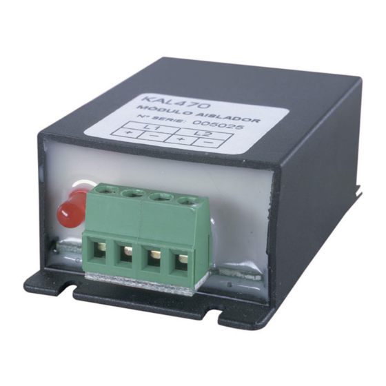
The KAL470 isolator module protects fire panel loops from short
circuit conditions. The KAL470 does not require an address on the
loop.
I
NSTALLATION
The KAL470 isolator module must be inserted between devices on
the analogue loop to guarantee protection in case of a cable short-
circuit. An LED on the unit will indicate that isolation is in effect.
For connection details see figure
T
S
ECHNICAL
PECIFICATIONS
Supply voltage.................................................................. 22-38 VDC
Current consumption .............................. (Quiescent @ 24 V) 110 µA
Current consumption .............................. (Quiescent @ 35 V) 135 µA
Alarm ........................................................................................10 mA
Storage temperature ...................................................... -10 to +50°C
Operating temperature ................................................... -10 to +50°C
Relative humidity (non-condensing) ........................................0-95 %
Dimensions...............................................................75 x 45 x 28 mm
© 2004 GE Interlogix B.V.. All rights reserved.
Version 2-2 / August 2004
55347003
.
KAL470 Isolator Module
Guía de instalación
KAL470 Conexionado eléctrico: 1 Pantalla; 2 Detector (o
cualquier otro elemento del sistema); 3 Módulo aislador.
D
ESCRIPCIÓN
El módulo KAL470 protege el lazo de la central de corto circuito. El
módulo no necesita una dirección en el sistema.
I
NSTALACIÓN
El módulo KAL470 tiene que ser insertado entre los elementos del
lazo para asegurar aislamiento. El LED indicará que el aislamiento
esta activo.
Para conexionado eléctrico ver figura
C
T
ARACTERISTICAS
ECNICAS
Tensión de alimentación .................................................. 22-38 VDC
Consumo en reposo (@ 24 V).................................................110 µA
Consumo en reposo (@ 35 V).................................................135 µA
Alarma ......................................................................................10 mA
Temperaturas del almacenado........................................-10 a +50°C
Temperaturas de trabajo .................................................-10 a +50°C
Humedad relativo ....................................................................0-95 %
Dimensiones............................................................ 75 x 45 x 28 mm
Installation Guide
.
Publicidad

Resumen de contenidos para GE KAL470
- Página 1 ESCRIPCIÓN The KAL470 isolator module protects fire panel loops from short El módulo KAL470 protege el lazo de la central de corto circuito. El circuit conditions. The KAL470 does not require an address on the módulo no necesita una dirección en el sistema.
- Página 2 Loop. NSTALLAZIONE Il modulo isolatore KAL470 deve essere inserito tra i dispositivi del Loop analogico per garantire protezione in caso di corto circuito su un cavo ed isolare solamente la linea interessata dal guasto. Un LED sull'unità...


