Tabla de contenido
Publicidad
Idiomas disponibles
Idiomas disponibles
Enlaces rápidos
!
Installation Guide
1
Electrical connections:
3
supply connectors;
Input connectors;
5
6
Status LED;
Resistor (alarm 2);
8
Resistor (standby).
D
ESCRIPTION
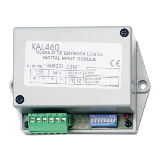
The KAL460 provides a remote input to an analogue fire detection
system. The input signal is constantly monitored and its status
communicated to the fire panel. The module has five possible
states: standby, open-circuit, short-circuit, alarm 1 and alarm 2.
The input does not have polarity and may be activated by closing
or opening a potential free contact (depending on the module
configuration).
The status LED is lit constantly during alarm.
I
NSTALLATION
For general guidelines on fire system planning,
design, installation, commissioning, use and
maintenance refer to the EN54-14 (2001) standard
and local regulations.
© 2005 GE Interlogix B.V.. All rights reserved.
Version 2-2 / July 2005
1052513
2
Loop connectors;
Auxiliary power
4
DIP Switches;
7
Resistor (alarm 1);
KAL460 Addressable Input Module
The module is designed for cabinet installation and must be
protected against environmental agents. The power supply should
be disconnected during installation.
The 24 V power supply can be taken from the loop or from an
auxiliary power source.
If more than 10 KAL400 series modules are connected to a loop,
an auxiliary power supply is recommended. Always verify large
installations using the loop load calculator to confirm that enough
power is available on the loop.
Power supply configuration
To set the module power supply remove the unit cover and
configure jumpers JMP1 and JMP2. See Figure 2: power supply
jumper configuration.
Figure 2: power supply jumper configuration
Loop powered.
24 VDC auxiliary power supply.
Installation Guide
Publicidad
Tabla de contenido

Resumen de contenidos para GE KAL460
- Página 1 ESCRIPTION power is available on the loop. The KAL460 provides a remote input to an analogue fire detection Power supply configuration system. The input signal is constantly monitored and its status To set the module power supply remove the unit cover and communicated to the fire panel.
-
Página 2: Technical Specifications
Para probar se transmite una señal al dispositivo y comprobar que ESCRIPCIÓN el mensaje de activación sale en la central. El KAL460 dispone una entrada remota a una central de control e Si el piloto indicador y la central de la instalación no indican la indicación analógica. -
Página 3: Guida All'installazione
Per provare il modulo, agire sul segnale (contatto) di ingresso dell'unità e verificare che il messaggio di attivazione sia Il modulo KAL460 fornisce un ingresso remoto per un sistema visualizzato sulla centrale antincendio. antincendio analogico. Il segnale di ingresso viene monitorato... -
Página 4: Especificações Técnicas
Consumo de corrente - Alimentação aux. de 24 VDC (alarme) .................< 50 mA • Steht er auf OFF, arbeitet das Modul mit normal geöffnetem Kontakt (NO). Consumo de corrente – alimentação por loop (repouso)..750 µA Im ersten Fall befindet sich der Eingang im Ruhezustand, wenn Consumo de corrente –... -
Página 5: Installatie
NDERHOUD EN TESTS ESCHRIJVING Het onderhoud is beperkt tot een jaarlijkse inspectie. Wijzig nooit De KAL460 maakt een externe ingang naar een analoog de interne bedrading of circuits. brandmeldsysteem mogelijk. Het ingangssignaal wordt continu Als u de module wilt testen, voert u een ingangssignaal naar de... -
Página 6: Руководство По Установке
ему числовой адрес в диапазоне от 128 до 253. Он О ПИСАНИЕ устанавливается помощью переключателей DIP 1-7 (см. KAL460 оснащен шлейфным входом для аналоговой системы таблицу 1: настройка адреса с помощью переключателей DIP). Переключатель DIP 8 используется для настройки пожарной... - Página 7 Table 1 / Tabla 1 / Tabella 1 / Tabela 1 / 1 2 3 4 5 6 7 8 1 2 3 4 5 6 7 8 1 2 3 4 5 6 7 8 1 2 3 4 5 6 7 8...


